1

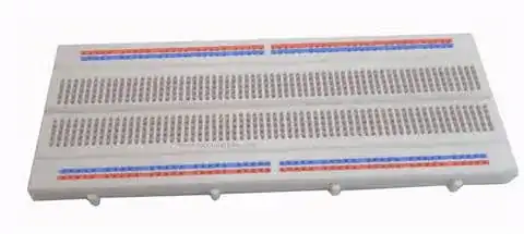
From my searches of the web ( as well as this question ), I have found that breadboards - like the one on picture - aren't a good idea when your application involves high frequencies.

Breadboard

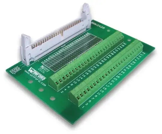
I am going to start making simple projects using STM32F407VG microcontroller, that can operate at frequency of 168 MHz. Although pin switching won't take place at this maximum frequency, it will still be very high, in orders of tens of MHz I assume. I have STM32F4 Discovery evaluation board, but will connect external circuitry to it as well.

My questions is : how should I build prototype circuits to avoid problems with parasite capacitance / inductance, if using breadboard is a bad idea ? Thank you.

James C
  • 652
  • 2
  • 9
  • 19
  • What's the highest external frequency you'll have on the breadboard? They can sometimes work fine if it's just the internal clock of the processor that's fast. I really don't see a way to "breadboard" for fast operation. Make a prototype PCB which is correctly designed and re-spin it for final product. – AndrejaKo Feb 14 '14 at 22:43
  • @AndrejaKo - thank you for comment. I have edited my question a little, I think it is clearer now. Prototype PCB is surely the best way, but not the easiest and quickest one. That is exactly the reason why I am posting this question =) – James C Feb 14 '14 at 23:01
  • @JamesC - what circuitry will you be routing onto the breadboard? What rates will it run at? Normally, if you avoid obvious culprits such as USB or the Ethernet external PHY signals, then there's nothing that *needs* to be fast going across your breadboard. You can also configure the I/O speed of driven pins for slower edges. Your question hints you are trying to get an *experiment* to *work*, not trying to build a *product* which generates minimal RF interference to *other* devices - if that were instead the case, then the breadboard would have to go. – Chris Stratton Feb 14 '14 at 23:03
  • @ChrisStratton - initially it will be common Arduino style sensors, camera and colour LCD display. Eventually it will also be radio control signals transmitter, communication with PC and the like. – James C Feb 14 '14 at 23:06
  • If you are using anything you can hang on an Arduino or typical contemporary SPI or async serial interfaced RF module you are unlikely to have a problem; if you were doing your own RF circuitry then the breadboard would be a bad choice. – Chris Stratton Feb 14 '14 at 23:07
  • @ChrisStratton - thank you for your comments. Can you please explain me why modules shouldn't produce problems, but my own RF circuitry may ? – James C Feb 14 '14 at 23:10
  • Because the base frequency of signals which can be used with Arduino-class modules is relatively low - often in the KHz range up to single-digit MHz. Low frequency RF systems might barely work but could be subject to interference from the digital signals. Higher frequency systems (UHF up to 2.4 GHz) probably wouldn't be impacted, but definitely aren't things you build on a breadboard. Typically they are a QFN packaged chip with a big ground pad underneath and circuit layout is moderately important. But if you get that on a module, you typically only have low speed interfaces to it. – Chris Stratton Feb 14 '14 at 23:13

1 Answers1

1

Fortunately, if you're using the internal clock, that 168MHz doesn't ever get to the breadboard. Think of your max frequency as what's going on at the pins.

For that processor, though, the simplest way to go is to pick up the stm32f4 discovery board for about $15, and do your prototyping with that. The useful pins are all broken out for you.

To get the signals you need from the Discovery board to something you can get at more is easy. I like using 50-pin ribbon cable breakouts. I use them to bring signals to breadboards, but they'll also bring them to solderable things like vectorboards. The ribbon cable, of course, attaches directly to the Discovery board headers.

This is all intermediate steps, of course. Eventually, when the bits and pieces of the design are all finished, you can print up a PCB with confidence, and move everything there. If I may offer advice, though, a 100 pin package with 0.5mm pitch isn't necessarily the friendliest way to break into surface mounted devices.

enter image description here enter image description here

Scott Seidman
  • 29,274
  • 4
  • 44
  • 109
  • Thank you for comment. In fact I do have that board. I know that pin switching won't take place at 168 MHz, my choice of words was probably not the best. I wanted to say that even if circuit itself won't reach the f. of 168 MHz, it will still be very high, in orders of tens of MHz I assume. I will edit my question. – James C Feb 14 '14 at 22:57
  • The alternative to the discovery dev board is really to print a PCB. Are you quite sure your pins will really be running at 10's of MHz?? I've done digital protocols at 100's of KHz on breadboards, and you should be able to run at 2MHz or so, maybe even higher, without problems. – Scott Seidman Feb 14 '14 at 23:04
  • There is a similar discussion in other comments, there are a few answers. I am not really sure about 10's of MHz, that is my guesstimation =) I believe I should be prepared for this as well, and know what to ( not ) expect from the breadboard circuit. – James C Feb 14 '14 at 23:08
  • 1
    You're the one driving when you use these, James. If you have stuff that needs to be handled at tens of MHz, then you have to deal with it, but if what you're doing doesn't require it, then you don't need to design it so there's high MHz at the pins. When I prototype w/ the Discovery board, I usually end up taking about a dozen pins from the board, and I have ways of making this easier that I'll edit my answer to include – Scott Seidman Feb 14 '14 at 23:31
  • I've run AVR's @ 20MHz on a breadboard without any issues. – jippie Feb 15 '14 at 08:31
  • Same here with PICs. Advising conservatively, perhaps overly so. We have the advantage of a scope, and can see misshaped pulses right away, but thats less clear to someone without a scope – Scott Seidman Feb 15 '14 at 12:18
  • @ScottSeidman - that's a great suggestion, about checking the pulse shapes. Can you get a clear enough sign that way, that something is not ok ? Or can some frequency related issues still elude our eyes ? By the way, you can edit your answer to include all that info, I think it will be of great value for all viewers. – James C Feb 15 '14 at 15:38