2

Electret amp

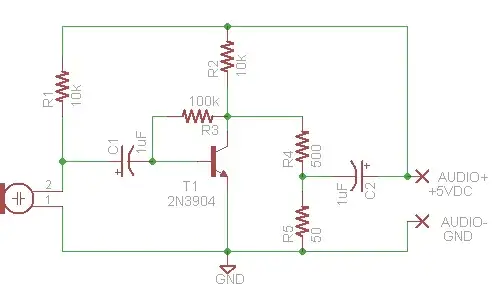
I'm attempting to create a converter box that allows the use of a standard electret mic and earphones as a headset for general aviation. The headset is relatively straight forward, just use an audio transformer to get a decent impedance match (~150 Ohm for the avionics output vs 8 Ohm for the headset). The mic is a little more difficult. In order to be compatible with WW2 era carbon mics, the avionics expect an input of ~0.5-1V and ~400 Ohm impedance. The avionics supply phantom power (or in the case of an actual carbon mic, DC bias). The actual voltage supplied seems to vary quite a bit, but 5-7 VDC seems to be typical. I've thrown together the above circuit to amplify the electret output and hopefully get the impedance close based on this answer, but I'm an ME by training and my analog circuit design skills are a bit rusty so I wanted to get some feedback from the community. My thought process is to combine the inverting amplifier with a voltage divider to get the output voltage and current into the desired range. I'm not sure that C2 is necessary since the audio+ line is already carrying a DC offset, but I figured it couldn't hurt. Is this approach at least on the right track? Thanks in advance!

EDIT: I haven't had time to pick up the components yet, but I was in the plane today and decided to try the mic as is with no additional circuitry. The mic was only faintly audible, which is about what I expected. Based on this I'm planning to try out Andrew's circuit once I get the parts. I'm also thinking of just replicating the electret's internal amplifier by hooking up a jfet as a backup plan.

EDIT 2: I was able to test Andy's circuit this afternoon and it worked well. The only change I made was to reduce the 100 ohm resistor to 10 ohms to increase the gain slightly.
Chain_Reaktion
  • 23
  • 1
  • 1
  • 4

1 Answers1

0

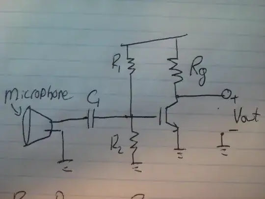
I think you may be overcomplicating this a little bit - why don't you just connect the electret microphone (observing polarity) to the microphone wires via a 3.3Kohm resistor and see what happens.

Your circuit won't work as it stands because the signal you are trying to put back onto the line gets fed back to the microphone via the 10k and it'll all end up very low gain in my humble opinion.

I don't think there is a substitute for trying it out and if it's not loud enough, putting a 10uF capacitor across the 3k3 resistor I mentioned and if that doesn't sound like the right volume maybe drop the 3k3 to 1kohm.

As for matching the impedance - this won't make a great deal of difference to the kit that recieves the signal. It's likely got an unbalanced input and is probably not differential so I don't think you need to jump thru hoops on this.

If you still believe the mic on its own won't work, try this: -

enter image description here

Andy aka
  • 434,556
  • 28
  • 351
  • 777
  • I'm a bit shaky on your proposed solution. Even with a built in FET, electret mics typically have an output on the range of 10-100 mV according to all my research, so it seems like I'm going to need some kind of amp to get it up to 0.5-1V. The original thought was that although the small amplitude signal will get fed back via R1, it will also feed through the transistor base, creating a much larger amplitude signal through R2 and the transistor, which then gets tailored to the proper amplitude via the voltage divider and put back on the line. Am I way off base here? – Chain_Reaktion Feb 12 '14 at 19:55
  • No this won't happen - the signal produced at the collector of the transistor will be exact anti-phase of the signal on the base - the amplitude will get smaller. – Andy aka Feb 12 '14 at 20:05
  • Although the common emitter amplifier is inverting, it does still amplify in this scenario, right? An instantaneous -10mV signal from the mic will create a 1V delta b/w collector and emmitter (assuming a gain of 100), implying ~4V at the collector. I'm don't mean to be difficult here, just trying to understand. Even if this circuit won't work (and I believe you when you say it won't) I will still need some kind of amplifier, won't I? Is it possible to power said amp using the same phantom power as the mic or do I need a separate supply? Thanks! – Chain_Reaktion Feb 12 '14 at 20:31
  • Well, you could make that same argument with an op-amp - even though it's got massive open loop gain, when negative feedback is applied that gain drops to a controlled amount but nobody would bother to say that the voltage at its inputs x open loop gain = voltage at its outputs - what happens with neg feedback is that it massively reduces the input voltage to the point that it is called a virtual earth. – Andy aka Feb 12 '14 at 21:11
  • If you want to try the circuit out then forget about R4, R5 and C2 - connect the collector directly to the phantom feed line. Put maybe 100 ohms in the emitter and split the 10k to the base into 2 x 4k7 with the centre point connected to ground with a 100uF capacitor. This may work BUT so might just trying the mic directly. – Andy aka Feb 12 '14 at 21:13
  • See adds to answer dude. – Andy aka Feb 12 '14 at 21:25
  • I'll definitely try both ways you suggest and see how it goes. The only question I have is that you've marked 2V across the electret. Where does that come from? – Chain_Reaktion Feb 12 '14 at 22:04
  • The ~2V comes from experience having seen a few electret circuits - note the about symbol ~ LOL. Good luck and please do come back and let me (us) know how you went on with it. Seriously. – Andy aka Feb 12 '14 at 22:22
  • @ Andy aka : That circuit of yours above works great. I just found this thread while searching for a similar solution replacing a carbon mic in a standard old dial telephone. I put a bridge rectifier in circuit to take care of any incorrect wiring polarity on phone lines and dropped the 100 ohm emitter resistor to 10 ohms which increased the gain nicely and compensated for the voltage drop introduced by the bridge. Many thanks. –  Sep 14 '15 at 02:18
  • @Andyaka Quick question, I see 2 GND in your circuit can you explain to me? I'm trying to test the circuit in my airplane but I only have Mic-Hi and Mic-Lo so I'm wondering if both GND are Mic-LO Thanks – exomic Apr 10 '20 at 22:22
  • It's just a doubling up on node labels and one ground symbol/name is sufficient. The ground node can have any name so mic-Lo is fine. – Andy aka Apr 11 '20 at 08:55