1

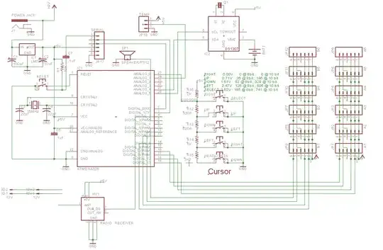
The strangest thing is happening to a standalone Arduino board that I've designed and built. The board (whose schematics are below) has the following features:

  1. It has an ATmega328P with a 5V voltage regulator.
  2. It controls a scoreboard with several 7-display digits linked through the connectors on the right (JP1 through JP12).
  3. It has cursor buttons decoded using a voltage ladder through ANALOG_0 (A0).
  4. It has a Real Time Clock to keep time when the board is turned off.
  5. It has an RF receiver module.
  6. It has a UART header (JP17) so I can program the board using a serial port.
  7. It has a speaker attached to digital pin 3 (D3).

My controller schematics

I upload firmware to it using a RS232-to-TTL adapter that I've also built (schematics also below) and a Serial-to-USB cable. When programming it, the board behaves much like an Arduino Severino board.

My RS232 to TTL adapter

What's strange is that, when I upload the firmware using Arduino IDE 1.03, the process is paused in the middle and then the speaker starts to beep continually. It just sits there waiting for me to do something. When I press reset on the board, the beep stops, the upload continues and the firmware is uploaded successfully to the board.

So, my questions are:

  1. What is making the upload process pause?
  2. Why is the buzzer beeping when the process pauses?

PS. This is a cross post from the newly created Arduino private beta site, but I thought that the question would be on-topic here, too.

Ricardo
  • 6,134
  • 19
  • 52
  • 85
  • A bug in the firmware. – Ignacio Vazquez-Abrams Feb 12 '14 at 01:23
  • @Ignacio - You mean a bug in the firmware (my sketch) that's already loaded and that I'm trying to replace? Or do you mean the bootloader? I'm pretty sure the same problem would happen if I loaded the blink sketch and repeated the process. In any case, I just can't see how the previous sketch can affect the one I'm trying to load (unless it was using the serial port at the same time as I'm trying to use it for uploading the sketch, which it is not). – Ricardo Feb 12 '14 at 01:29
  • 1
    I wonder if the problem is cause by the RS232 translator you are using. Have you tried to use a dedicated RS232 chip like max232 to see if it solves the problem? – alexan_e Feb 12 '14 at 08:47
  • @alexan_e - That's a good idea! That translator is also used in [Arduino Severino (S3V3)](http://arduino.cc/en/Main/ArduinoBoardSerialSingleSided3) and it causes me problems there, too. I have a couple of those MAX232 ICs collecting dust in one of my bins. I'll put one of them to use, just to be sure. – Ricardo Feb 12 '14 at 10:48
  • 1
    These RS232 level translators using transistors depend on the transmitted signal (Tx, from mcu to PC) to charge the pump capacitor and in general are not very reliable, especially when the balance between incoming and outgoing signal is not similar which may discharge the capacitor. To work properly you want to have more traffic from mcu to PC which I'm sure is not the case when programming the chip. – alexan_e Feb 12 '14 at 11:10
  • @alexan_e Your comment is the closest I got for an answer on this question, so if you turn it into a proper answer, I'l upvote it and accept it. Thanks! – Ricardo Apr 01 '14 at 12:22
  • Have you tried a MAX232 with the higher speed rate to see if it works? – alexan_e Apr 01 '14 at 12:35
  • @alexan_e - Oh yeah! I did! That was good advice!! And it did fix these beeping and pausing problems, but I had a few other problems as well. See details [here](http://electronics.stackexchange.com/questions/104466/problems-with-homemade-rs232-to-ttl-converter-board-based-on-tis-max232) and [here](http://electronics.stackexchange.com/questions/104901/speed-problems-in-homemade-rs232-to-ttl-converter-board). But it's been a great learning experience, too!! – Ricardo Apr 01 '14 at 12:40

1 Answers1

1

I finally found what was causing the problem: the reset signal from pin 4 (DTR - Data Terminal Ready) on the DB9-Female connector was spiking up to 10V before going to 0V and was triggering high-voltage programming on the ATmega. Below is a scope shot showing the situation:

Scope shot showing voltage spike to 10V

The yellow trace is DTR signal while the green trace is the RESET signal on the ATmega.

According to Atmel's Atmel AVR042: AVR Hardware Design Considerations application note, one should add an ESD diode between ATmega's RESET and Vcc to prevent the reset signal from triggering high-voltage programming mode, like so:

Recommended RESET pin connection for ATmegas

After adding such a small signal diode (1N4148) like the app note recommended, I got the issue fixed. See below the scope shot taken after the diode was added.

Scope shot after fixing the board

Now the 10V peak is gone.

That was a tricky one!! But I could never find what was wrong without research and the right tools. Money on a scope is money well spent!!

Ricardo
  • 6,134
  • 19
  • 52
  • 85