12

This is my first post. I'm a software guy trying to do hardware so be gentle :)

Circuit

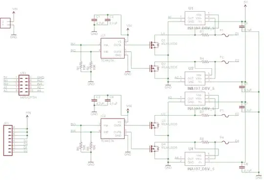
I'm designing a small circuit (see pic, and sorry for messy schematic) that plain and simply is a bunch of MOSFETS and gate drivers designed to switch resistive loads (heating pads in this case) from a microcontroller. The heating elements often has a very low resistance, and to keep power at the desired level, the MOSFETS are switched using PWM.

Measurement

Besides the purely functional aspect, there's an educational focus as well. I want to be able to get some feedback on the current consumption. And my naive approach was to simply throw in some current shunt sensor IC's. When using a multimeter to measure the output voltage from the sensor, I actually get something that looks like the average current (with PWM switching) due to the "slowness" of the ammeter. But when connecting same output to i.e. an atmega328p ADC, I get some bad readings - the speed here puts a reading anywhere on the PWM square wave.

So, my question is how do I go about measuring the (average) current when switching with PWM?

It seems the design is OK, but I might have missed something in both the design and how the uC ADC should be used in this context.

schematic

RawBean
  • 857
  • 6
  • 17
ltj
  • 163
  • 1
  • 6
  • I think a filter could be used to give a mean voltage from the PWM. An interesting article that explains such a filter and the values used based on the PWM frequency is [this one](http://dev.emcelettronica.com/how-to-use-pwm-to-generate-analog-or-analogue-voltage-digital-circuits-part-2). – alexan_e Feb 09 '14 at 11:31
  • There are some related answers in [this question](http://electronics.stackexchange.com/q/95546/29792). But they just mention using shunts and ICs to measure current. There's no mention of PWM, though. – Ricardo Feb 09 '14 at 11:33
  • Thanks for the comments. @alexan_e: TI is showing an input filter in the INA197 datasheet, but I was unsure of its use. It might be the way to go when not having stable voltage. – ltj Feb 09 '14 at 12:15
  • I think it is the solution to your problem but I'd rather have someone more experiences on this provide a detailed answer, that is why I posted this as a comment. – alexan_e Feb 09 '14 at 12:20
  • As the output is variable duty cucle PWM, you could use a peak detector circuit and measure that with an ADC. – Martin Feb 09 '14 at 20:21

2 Answers2

6

Sometimes what looks simple is not that simple. You have a quite complex measurement to do, but you want a simple result. What you want to measure is not constant, it's varying in time. Depending on your level of requirement, you could compute one or many properties of the current consumption. These properties will help you to better monitor the system. I propose you 3 different solutions, in ascending complexity.

Solution 1: Average

You want to get a one-value result -> get the average in time. As already proposed by @akellyirl, use a low-pass filter. Compute float y = alpha*input + (1-alpha)*y for each sample, where alpha is the smoothing factor. See Wikipedia for the details.

Solution 2: Max + Average

You are interesting in getting the average, and the max value. Monitoring the max value could be interesting for component dimensioning for example.

if (y > max)
  max = y;

Solution 3: Standard deviation + Max + Average

Why?

See below charts. There are 3 signals of different shapes. A triangle, a sine, and a spike signal. They are all periodic with same period, same amplitude, same average, and same min and max. But, they have different shapes, and indeed they have a completely different story...
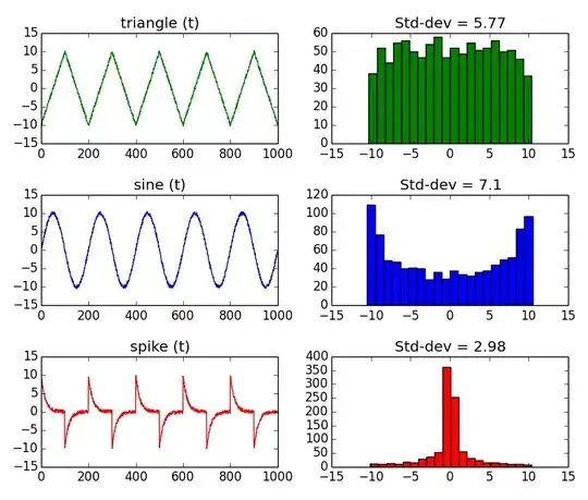
Signals and their histogram

One of the difference is the standard deviation. That's why I suggest you to extend your measurements, and include the standard deviation. The problem is that the standard way to compute it is CPU consuming. Hopefully, there is one solution.

How?

Use the histogram method. Build an histogram of all the measurements, and extract efficiently the statistics (min, max, avg, standard deviation) of the dataset. The histogram groups values together that have the same value, or same range of value. The advantage is to avoid storing all the samples (increasing count in time), and to have a fast computation on a limited number of data.

Before starting acquiring measurements, create an array to store the histogram. It is a 1 dimension integer array, of size 32 for example:

int histo[32];

Depending on the range of the ammeter, adapt below function. For example, if the range is 256mA it means that bin 0 of the histogram will be incremented by value between 0 and 8 mA, bin 1 by value between 8 and 16 mA etc...So, you'll need an integer to represent the histogram bin number:

short int index;

Each time you get a sample, find the corresponding bin index:

index = (short int) floor(yi);

And increment this bin:

histo[index] += 1;

To compute the mean, run this loop:

float mean = 0;
int N = 0;
for (i=0; i < 32 ; i++) {
  mean = i * histo[i]; // sum along the histogram
  N += i; // count of samples
}
mean /= N; // divide the sum by the count of samples.
mean *= 8; // multiply by the bin width, in mA: Range of 256 mA / 32 bins = 8 mA per bin.

To compute the standard deviation, run this loop:

float std_dev = 0;

for (i=0; i < 32 ; i++) {
  std_dev = (i - mean) * (i - mean) * histo[i]; // sum along the histogram
}
std_dev /= N; // divide the sum by the count of samples.
std_dev = sqrt(std_dev); // get the root mean square to finally convert the variance to standard deviation.

The strategy of the histogram method is to make the slow operations on a few number of bins, instead of all the acquired signal samples. The longer the sample size, the better. If you want more details, read this interesting page The Histogram, Pmf and Pdf.
RawBean
  • 857
  • 6
  • 17
  • very thorough and clear explanation. On a practical level, how do you ensure that the ADC sampling is distributed "in a good way" i.e. not locked in with the PWM signal in any way? I must admit that right now I just use the Arduino (hw + sw) for both PWM and ADC sampling. It might be that I should setup the built-in timers myself. I guess the sampling frequency should be quite a bit higher that the PWM frequency right? – ltj Feb 14 '14 at 09:12
  • 1
    As soon as you start sampling, the things get quite complicated. The first thing to do, is to keep in mind is the Nyquist-Shannon theorem. What is intuitive is that the higher the sampling frequency, the more information you have. But what is not intuitive, although fundamental, is that before sampling at frequency Fs, you must *absolutely* low-pass filter (in the analogic/electronics domain) the signal at Fs/2. Otherwise, you will be impacted by the aliasing. I suggest that you choose the highest sampling frequency. Something like ~10 times the PWM frequency if possible. – RawBean Feb 14 '14 at 14:46
  • This is a common misunderstanding of the Nyquist-Shannon theorem which actually states that need you to sample at twice the bandwidth. Aliasing can be helpful. No disrespect intended, but this seems like an answer from a texbook. Suggesting a ~10 times PWM sampling in this scenario when high frequency detail is most likely irrelevant is overkill. – akellyirl Feb 16 '14 at 13:11
1

You understand the problem correctly: you need to get the "average" of the PWM, just like the meter you're using for measurements.

You could use an RC filter on the A1,2,3 signals whose time constant is at least ten times your PWM period. That means if your PWM period was 10 microseconds then the RC time constant should be 100 microseconds. For example 10kOhms x 10nF = 100us

A better solution is to filter the signals digitally in the microcontroller like this:

float y = (1-0.99)*input + 0.99*y; 

Change the "0.99" value to change the time constant of this digital filter.

akellyirl
  • 4,117
  • 1
  • 16
  • 30
  • 1
    Watch out for aliasing if you do it in code. – Andy aka Feb 09 '14 at 14:46
  • Aliasing is not necessarily a problem. We all know that to reconstruct a signal the sample rate must be at least twice the highest frequency. But when the signal is bandlimited you only need to sample at twice the *bandwidth*. This is called undersamplig. As the signal is presumably low frequency because it's driving a heating pad, then reasonable sample rates in 100 to 1000 SPS range should be fine. See: http://www.ni.com/newsletter/50078/en/ – akellyirl Feb 09 '14 at 15:26
  • Would be wise to make sure the PWM rate and the sample rate are mutually prime if using undersampling. – akellyirl Feb 09 '14 at 15:33
  • Precisely my thoughts - if measuring via ADC and generating PWM in same MCU, there may be a tendency for both to be locked in time. – Andy aka Feb 09 '14 at 15:35
  • The signal is at pwm frequency, not low freq. If it were low frq, its probably less resource intensive to simply sample over one period and average than to use floating point math that way. – Scott Seidman Feb 09 '14 at 15:47
  • As I see it the signal is low frequency modulated onto a PWM carrier. The current signal *could* have high frequency content that needs to be preserved. But that doesn't look like this situation from the description. – akellyirl Feb 09 '14 at 15:56
  • Thanks all. I will play around a bit with the software filter and see where it gets me. @akellyirl, if I understand you correctly you suggest (if hardware RC filter was chosen) a filter on the sensor output. But the datasheet says it would be better to put it on the input? Also, could you please elaborate on why a SW filter is better? Thanks. – ltj Feb 10 '14 at 07:11
  • Putting the filter on the input is complicated by the low input impedance of the INA197 causing offsets that you need to take some care to reduce (as described in the datasheet). Putting the RC on the output is simpler. You lose the advantage of the very low output impedance of the INA197 (which is good for driving loads), but the Atemga328P data sheet says "The ADC is optimized for analog signals with an output impedance of approximately 10 kΩ or less. If such a source is used, the sampling time will be negligible". So using a 1kΩ resistor should be fine. The dig filt requires no components. – akellyirl Feb 10 '14 at 10:02