0

I want to sense mains voltage at a frequency faster than 5000Hz, with a microcontroller. The idea behind this is to visualize the actual shape of the AC voltage, and eventually to compare it with the current to determine its cosphi.

I have read that I need to use a optoisolator to isolate both circuits. How do I choose which one I need for an analog output of the scaled voltage?

Chris Stratton
  • 33,282
  • 3
  • 43
  • 89
tfjgeorge
  • 103
  • 2
  • Can you please provide a link to where you read that you should use an optoisolator in this case? Are there certain optoisolators that you are considering? – Joe Hass Feb 07 '14 at 17:37
  • Originally it said "sense mains voltage at a frequency faster than 5k" - I assumed this might have meant sample at 5k or above. I'm not sure that the modification/edit is correct based on that - it now implies samping at least 10kHz. – Andy aka Feb 07 '14 at 18:20

3 Answers3

1

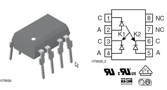
There are a number of analog optoisolators that will work for you. The Vishay (nee Infineon) IL300 is an old standard.

enter image description here

It is normally used in a circuit such as this:

enter image description here

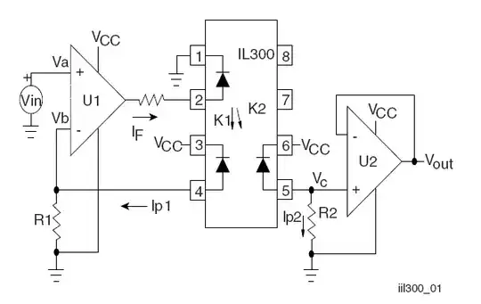
Because a single LED illuminates two photodiodes, the LED drift can be largely compensated by the closed loop feedback circuit.

Note that you require a power supply on the high voltage side, so you may require an appropriate DC-DC converter.

More accuracy is possible from more recently developed similar parts such as the HCNR201.

As others have said, there are a number of other galvanic isolation technologies, digital and analog (your signal could be digitized on the hot side, so there is some percentage in considering digital methods). Magnetic (analog and digital) and differential capacitor coupling are a couple of common ones. Some are modules that have an isolated power supply incorporated. Of course, price escalates rapidly as such features are added.

Spehro Pefhany
  • 376,485
  • 21
  • 320
  • 842
1

I would look into putting the microcontroller circuit on the hot side, have it do all the measurements by being directly coupled, then send the digital results over a opto. This gets around having to use analog optoisolaters. You will only be shipping digital information accross the isolation barrier.

Of course you have to be careful about touching anything on the hot side, whether that includes a microcontroller or not. Initial debugging should be done a isolation transformer, and preferably at lower voltages.

Olin Lathrop
  • 310,974
  • 36
  • 428
  • 915
  • Thanks ! Now something that is not clear in my mind: the microcontroller must be supplied with a 5V DC power supply. Does it share the same ground with mains voltage ? – tfjgeorge Feb 12 '14 at 16:34
  • @tfjg: You will need to arrange for 5V power for the micro on the hot side. If you buy something off the shelf for that, it will probably be isolated, so the ground reference can be whatever is most convenient for making the measurements. Otherwise, you can probably use something like a capacitive charge pump that uses the AC line frequency for the pumping. I'd probably use the AC ground as the microcontroller ground then. That works with the charge pump and should be useful for making the measurements. – Olin Lathrop Feb 12 '14 at 17:19
0

Use a regular voltage transformer rather than an opto coupler - it will provide the isolation (safety) and give you a decent linear analogue signal to feed into your MCU.

When you come to look at current use a current transformer. Feed the single wire thru the CT's hole and you get a decent representation of current across its burden resistor.

If you are going to calculate power factor (I'm presuming that's what you meant by Cos Phi) be prepared for significant errors - you can't just use zero crossing algorithms unless the current is particularly clean and free of harmonics. See this answer - it may help you understand how tricky it may be to measure power factor.

Andy aka
  • 434,556
  • 28
  • 351
  • 777
  • I wonder if typical transformers designed for power applications have the bandwidth to pass the entire signal of interest? – Chris Stratton Feb 07 '14 at 18:13
  • @ChrisStratton if you are interested only in calculating power factor then you are only interested in fundamental frequencies (with the assumption that the voltage waveform is virtually sinusoidal). Apart from the fact that power transformers deliver the power to your home in the first place!! – Andy aka Feb 07 '14 at 18:16
  • 1
    The poster expressed an explicit interest in getting a wider bandwidth view. Many types of power supplies do in fact introduce distortions at other than the fundamental frequency - that may not strictly qualify as "power factor" but it can be of interest and actual concern. While transforms involved in power delivery may attenuate these to some degree, an *instrument* is hopefully designed to reflect as true a measurement as possible, without introducing additional rolloff in the bandwidth of interest. – Chris Stratton Feb 07 '14 at 18:19
  • @ChrisStratton I agree with what you say - wider bandwidth is better of course but I took the meaning of the question to be "sampled" at 5kHz which you've subsequently altered to bandwidth of 5kHz upping S to 10kHz. It's just my impression of what he said. – Andy aka Feb 07 '14 at 18:24
  • The \$ cos(\phi) \$ implies it's sinusoidal, but 5kHz implies a lot of harmonic content. Hard to tell without ESP. – Spehro Pefhany Feb 07 '14 at 20:58
  • @SpehroPefhany power factor is the same with or without harmonic content on current providing no harmonics on voltage. With a clean voltage sinusoid you can rigourously LP filter both V and I identically and still get PF. – Andy aka Feb 07 '14 at 21:01
  • @Andyaka Wouldn't that give you the displacement power factor rather than the real power factor? – Spehro Pefhany Feb 07 '14 at 21:14
  • @SpehroPefhany if voltage is sine then any harmonics on current does not contribute to average power therefore PF (Cos phi) only applies to fundamental frequency. – Andy aka Feb 07 '14 at 21:31
  • @Andyaka Ok. I do wonder how realistic an assumption that is. – Spehro Pefhany Feb 07 '14 at 21:35
  • @SpehroPefhany what happens when you multiply two sinewaves of different frequencies, harmonically related or not? – Andy aka Feb 07 '14 at 22:02
  • @Andyaka The assumption of no distortion on the voltage. Is that realistic? – Spehro Pefhany Feb 07 '14 at 22:22
  • @SpehroPefhany No it's not realistic if you want pin-point accuracy. Where are we going with this interesting discussion dear chap? Consider this, if PF is to be calculated (as per what the OP wants and this is quite reasonable to an accuracy of a few degrees/%) and there is harmonic content on volts and amps, it becomes a bit of a mess if the power from the harmonics is significant. It, more than likely will not have the same PF thus a multitude of harmonic PFs would need to be uncovered. This is best left for questions like - how do I improve my PF measurement!!! – Andy aka Feb 07 '14 at 22:43