I'm trying to drive a 7-segment common anode, in the following connection, however there is no output the comes from the ULN2003 at all, its like when it gets a 0 in the input, it gives a tri state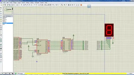 output.
Asked
Active
Viewed 1.3k times
3
Joe Hass
- 8,447
- 1
- 29
- 41
andre_lamothe
- 496
- 1
- 7
- 23
-
If your 7-segment dipslay is in fact red, it may be dead already. The 74HC595 outputs a 5V signal, and you don't have any resistors in there. The red LED takes a 2V forward voltage. Let me know – Funkyguy Feb 07 '14 at 02:55
-
@ShannonStrutz I put current limiting resistors between the ULN and the 7-segments still they don't work. Kindly note that the above schematics is in proteus simulator. – andre_lamothe Feb 07 '14 at 03:51
-
If you just did it though, like after you turned it on for the first time, it is likely dead already. Your 5V signal would have blown them out. If you did it before you turned it on for the first time, then I don't see anything wrong with it and in that case I would ask what led you to believe it was the ULN2003 not doing its job instead of the 74HC595? – Funkyguy Feb 07 '14 at 04:25
-
@ShannonStrutz The output from the 74HC595 is the same as I expected, so I get correct output from it, the problem is the output of the ULN2003 is partially correct; Zero's outputs are correct, but one's are like tristate, which means neither 1 or 0, just floats, which is really weird. – andre_lamothe Feb 07 '14 at 05:27
2 Answers
1
The circuit you show will work fine in reality (assuming that you also add the resistors in series with the display to limit the current).
In proteus it doesn't behave as expected, the open collector outputs of ULN2003 are not pulled high through the LED as they are supposed to be, this is a simulation model misbehavior.
The solution you can use it to add pull up resistors (I have used a resistor network) like shown below:
The shown schematic is valid for simulation only, the pullup network is not needed in the real circuit. You also have to add the series resistors to the segment lines which are omitted in proteus to improve the simulation speed.
alexan_e
- 11,070
- 1
- 28
- 62
-
@AhmedSaleh When you draw power supply symbols try to draw them pointing upwards for positive supply and downwards for ground (like in my schematic). Not everyone is familiar with the symbols of each schematic entry application so having a triangle pointing downwards can really confuse people who may interpret it as ground. – alexan_e Feb 07 '14 at 10:28
-
@alexan_w: when the common side of the display is indeed positive adding pullups doesn't serve any purpose beyond debugging. What IS needed is series resistors! – Wouter van Ooijen Feb 07 '14 at 10:32
-
@WoutervanOoijen I think I have made this very clear in my reply, please read what I wrote under the schematic. – alexan_e Feb 07 '14 at 10:39
-
@alexan_e In real circuit, If I want to multiplex several 7-segments, to the same ULN2003, Should I connect another current limiting resistors from the output terminals of the ULN2003 to the new 7-segment ? – andre_lamothe Feb 10 '14 at 20:48
-
1@AhmedSaleh one resistor per output is enough to limit the current. Refer to this [schematic](http://www.turbokeu.com/myprojects/ledclock/led-clock%20dcf%20ca1.gif) or [this one](http://www.electro-tech-online.com/attachments/mux-ca-png.12099/) – alexan_e Feb 10 '14 at 20:58
-
@alexan_e is it possible to use ULN2003 to multiplex other 7-segments too ? instead of using another set of transistors to switch the segments on/off? I'm actually trying to drive 32 7-segment using the above schematic. – andre_lamothe Feb 10 '14 at 21:07
-
@AhmedSaleh ULM2003/2803 can only drive the ground side (cathode). For the anodes you can use either transistors or similar devices designed to source current like [A2982](http://www.allegromicro.com/~/Media/Files/Datasheets/A2981-2-Datasheet.ashx) – alexan_e Feb 10 '14 at 21:15
-
@alexan_e Thanks, but I didn't mean that. I meant, is it possible to use the ULN2003 leads to control/switch another set of segments 9 ( their a,b,c,d,e,f,g) for example, with TDM and persistence of vision ? instead of using another 9 transistors connected to the segment VCC as shown in the schematics to turn them on/off for a specific period ? – andre_lamothe Feb 10 '14 at 21:19
-
@AhmedSaleh I'm not sure what TDM refers to. You mean have the anodes permanently ON and use one ULN2003 per segment for the cathodes? Yes, it can be done but I think it complicates things. – alexan_e Feb 10 '14 at 21:36
0
The ULN2003 is an open-collector driver, it can sink current towards ground but not supply current from Vcc. You will need to use a different display (common anode instead of common cathode) or use a different driver (open-emitter (or sourcing) drivers do exist, but they are not as common as the ULN2004/ULN2803.
Note that if you need to drive just one display, the HC595 can probably handle the current. Aim for a few mA per segment instead of the full 20mA. The difference in brightness will be much less than you'd suspect.
Wouter van Ooijen
- 48,407
- 1
- 63
- 136
-
The display he has used is common anode ("I'm trying to drive a 7-segment common anode") but I'm sure you were confused by the triangle connected to the display that points downwards like the ground. That triangle is the Vcc symbol in proteus, the ground is the earth symbol (three horizontal lines) – alexan_e Feb 07 '14 at 08:31
-
Yuk! I'll leave my answer as an example of the confusion that can arise from a downward pointing Vcc symbol. – Wouter van Ooijen Feb 07 '14 at 10:33
-
I can absolutely justify your assumption that the triangle pointing downward was a ground. I have left a comment to the OP about this under my reply. – alexan_e Feb 07 '14 at 10:37