I'm currently developing a open-source "Home-PLC" for home automation. Every thing runs fine so far and I have a module with fixed voltage AC inputs and outputs.
In the next step I want the build 'universal inputs' (power detection @ AC/DC 5..250V).
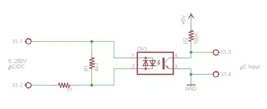
So I looked around and made some tests and have found a circuit that does what I want. But unfortunately I don't understand the circuit and I also don't know a part (??) in the circuit.
I exchanged the optocoupler with a LED and used inputs from 5 VDC to 230 VAC. The LED just works with almost the same intensity.
Text on the part "??" is MZ3. That is normally a PTC (Thermistor). The part has a resistance of 2.8 kilohm at room temperature. When holding the part tight in my fingers, resistance goes a bit down to 2.75 kilohm. Holding the solder iron close to the part the resistance is going down even more.
No idea how a PTC should work here!
Another thought was that the part is a CLD (current limiting diode). But CLDs normally are looking like diodes an not like this part:
(??-Part)
- Any ideas what the "??" part is?
- How does the circuit work?
- Any other ideas to build a "universal input" for less money?