I'm trying to get a voltage in a range from a potentiometer.
The potentiometer theorically varies between 22k and 40k (R1 in the shematic) but I'm unsure as I currently don't have it in my hands.
I want to "convert" the potentiometer value to a voltage in [0v-5v].
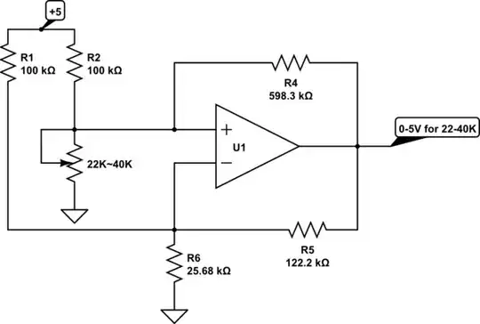
simulate this circuit – Schematic created using CircuitLab
Here, I first convert the impedance to a voltage trough a voltage divider (R2/R1+R2), and then I input this in a differential LIAO.
It should substract Vc from Va and multiply it with R4/43 and I should have : Vout = (R4/R3)(Va-Vc) which would give me a value in the right range.
But the problem is that It actually won't work because the second voltage divider won't just behave as if Va was a regulated voltage source, and with Thevenin theorem, you can find this equivalent circuit (here just for Va - Vb part) :
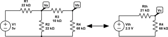
And then I have Vc = 1.91011 Volts while what I'd want there is Vc = 5*(22k/44k)(68k/78k) = 2.17949
How can i do ?