I need to convert a 4 V peak to peak signal (-2 V to +2 V) into a 0 to 3.3 V signal to get it into my ADC on LPC 11u24. I have tried several designs but the problem is that all of the designs I found are based on single rail op amps. I only have dual supply op amps. Any suggestions?
Asked
Active
Viewed 1,523 times
2
-
When you say 2v p-p do you mean bipolar like -1v to +1v (swinging above and below ground level) or just 0-2v ? – alexan_e Jan 30 '14 at 17:00
-
You could try shifting the signal by adding DC using a summing amplifier with unity gain. – Pyxzure Jan 30 '14 at 17:11
-
Oh Sorry I meant -2v to +2v – AntreasAntoniou Jan 30 '14 at 17:30
-
1`I only have dual supply op amps` Why is that a problem preventing you from using the solutions you found for single rail opamps? – alexan_e Jan 30 '14 at 18:26
-
You would add a DC voltage of 2V to the input signal so that its peak value is 0 to 4V. A diode voltage shifter which clamps the minimum to 0V is also possible. You convert this to 0V to 3.3V using a voltage divider or a b- directional level translator There seems no loss of resolution of signal in this way. – Amit M Oct 05 '22 at 15:01
-
Speed of the signal might matter in your design. For low speed, the above may work. For high speed a CMOS solution might be better. – Amit M Oct 05 '22 at 15:11
3 Answers
2
Based on this post, a summing amplifier could work. Adjusting the values, the schematic would be as follows:
simulate this circuit – Schematic created using CircuitLab
The output is calculated just like a non-inverting amplifier. Thus, when the sine wave is +2V, the terminals of the op-amp are at 2V. Since
\$V_O = V_I(1+\frac{R_4}{R_3})\$
the output will be 3.3V. When the sine wave is -2V, the terminals will be 0V, since the two voltage sources, \$R_1\$, and \$R_2\$ act as a voltage divider. Then the output will also be 0V.
The caveat here is that you need a rail to rail op-amp, or supply voltages that are less than 0V and greater than 3.3V. Otherwise the op-amp will clip the output.
Justin Trzeciak
- 1,617
- 1
- 14
- 19
-
There are also simpler, passive solutions here: http://electronics.stackexchange.com/questions/32318/how-can-i-measure-voltage-in-range-15v-to-50v-with-adc-in-microcontroller-in-a/32328#32328, http://electronics.stackexchange.com/questions/7583/how-do-i-sample-a-2-v-to-2-v-analog-signal-with-a-pic-microcontroller – Justin Trzeciak Jan 31 '14 at 13:06
0
This will level shift your +/-1V signal, however it requires a low impedance source and you lose a couple (1.7) bits of resolution.
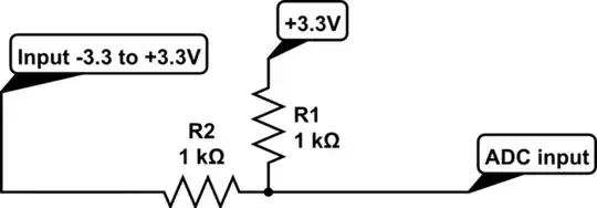
simulate this circuit – Schematic created using CircuitLab
Spehro Pefhany
- 376,485
- 21
- 320
- 842
-
-
The network above gives you a -3.3 to 3.3V range (6.6V p-p) as your signal is only 2V p-p, you lose \$log_2\$(3.3) bits. – Spehro Pefhany Jan 30 '14 at 18:03
-4
Use a non inverting amplifier with gain as 1.65.
This link could help you (http://www.instructables.com/id/Non-inverting-amplifier-with-uA741/?ALLSTEPS)
Harish_N
- 119
- 5