3

There are Smith charts with impedance and admittance coordinates and Smith charts with only impedance coordinates.

Smith charts

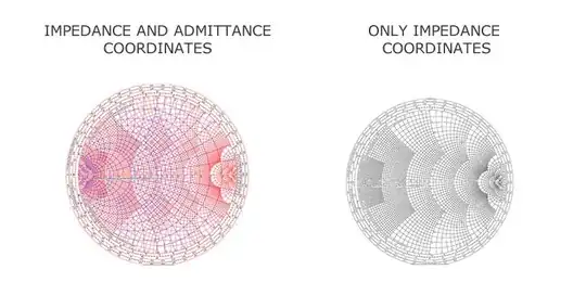
I believe I learned how to use the first one. Is there any sense in studying how to use the second one?

ivan
  • 179
  • 1
  • 12
  • 2
    The second one is just the first one with the blue lines removed. – The Photon Jan 22 '14 at 17:47
  • If your calculation doesn't require the admittance lines, it will stress your eyes less to use the chart on the right. – The Photon Jan 22 '14 at 17:49
  • 1
    For design, you almost always need the admittance lines. The impedance-only chart is for *displaying* impedance, such as on a vector network analyzer. – markrages Jan 22 '14 at 17:53
  • @Thephoton as you surely know when looking for parallel components it is necessary to use admittance coordinates and you can clearly see your options using the first chart while you need constantly to transform back and forth from impedance to admittance with a second one. – ivan Jan 22 '14 at 18:00
  • In that case, using the first one would make sense. But if you're just displacing an impedance back up the line, or calculating a stub length, for example, you could use the simpler chart. – The Photon Jan 22 '14 at 18:05

2 Answers2

2

Learning to use the chart on the right, by itself, is a good academic exercise but not very useful.

When using the YZ-chart on the left, the top half is inductive and the bottom half is capacitive. This is true for both series and parallel components. When the Z-chart on the right is used to draw admittance curves, everything is reversed. The top half is capacitive and the bottom is inductive. This is why a series inductor and a shunt capacitor follow the same path. It just adds unnecessary confusion.

curtis
  • 329
  • 1
  • 2
  • 11
1

The usage is exactly the same. Impedance \$Z\$ and admittance \$Y\$ are the same thing, described differently:

$$ Y \equiv \frac{1}{Z} $$

Adding the admittance lines to the chart just makes it easier to use in many cases. For example, when adding a parallel reactive component to the matching network you will move around the admittance circles. When the lines aren't drawn, as in the "impedance only" example, the same thing happens, but the lines aren't there to help you see.

Phil Frost
  • 56,804
  • 17
  • 141
  • 262
  • Here's an L-network [link](http://www.maximintegrated.com/images/appnotes/742/742Fig12.pdf). The length of arc A' through B gives the normalized susceptance value of capacitor connected in parallel. No moves around the admittance arcs. Source [link](http://www.maximintegrated.com/app-notes/index.mvp/id/742). – ivan Jan 22 '14 at 18:32
  • @ivan if you say so. Doesn't change the fact that for every point on the chart, there is an impedance, and an equivalent admittance, and you can chose to draw the lines, or not. That doesn't make impedance and admittance any less equivalent. http://www.fourier-series.com/rf-concepts/flash_programs/SmithChart_L_C_Match/smithchart_L_C_match.html – Phil Frost Jan 22 '14 at 18:45