In order to measure power (and sum that up to get the energy flow), the instrument needs to measure both the voltage and the current.
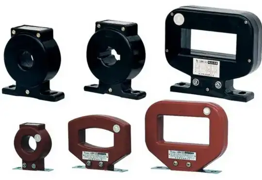
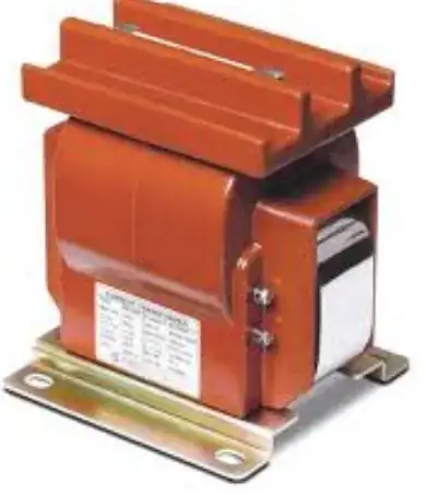
When voltages and currents are relatively low, it makes sense to run wires directly to the instrument, hence "direct connected". If the currents are relatively large, the wires become thick and expensive, and the control panel might be a bit remote. Also, the connections on a typical instrument won't handle very high currents. Such high currents can also be quite dangerous because fault currents could be high enough to cause arc flash injuries. So, a Current Transformer (CT) is installed on the high current line (typically a toroid or square donut shape and the high current wire simply passes through, forming a one-turn primary). The secondary current is much less, often 5 Amperes at full scale (which might be 100A or more on the main conductor).

The same thing is true of voltages- a 240V input is no problem with reasonable clearances, but a 1kV wire would cause headaches- thick insulation and danger. To solve this problem a potential transformer (also called a voltage transformer (VT) can be used to step the voltage down to something more compatible with instrumentation.

These items are classed as "Instrument Transformers". The operating principles are generally the same as any other transformer, but they are optimized for the intended application.
One interesting quirk is that a CT is typically operated with the output almost shorted so the input current determines the output current, and not the load. If the output load is removed from a current transformer (because the wire breaks, for example), there is quite a bit of transformer core in there (to get good accuracy under normal conditions), so the output voltage can rise enough to be a hazard to someone poking around.
For residential smart meters, every penny is important because of the high volumes, and some use high-current shunts (direct connect) but CTs are not unknown. In the below photo of a North American residential smart meter you can see the two "hot" lines pass through the CT in opposite directions. Since they're 180° out of phase, they add. Since the two hot lines are assumed to be balanced (in voltage), there's no need to measure the neutral current.


