4

I'm designing a Synchronous buck converter. I'm having doubts regarding the following:

  1. In the rectifying period of the converter, using a Schottky diode in parallel with the low side MOSFET will prevent the body diode from conducting, and so it should render the switching losses in this FET equal to zero. However I would expect that while the LS-MOSFET is switching it would be conducting at least a bit and therefore some losses would occur. Can you explain this to me, everyone just assumes there are no switching losses and that's that... And plus, are there any problems if a Schottky diode isn't used?

  2. Minimizing the losses in the diode conduction period equals to minimize the dead time between the signals that control both MOSFETs. While testing for a small dead time, I took it too far and had both FETs short circuited (even though I calculated the switching times according to the gate driving current). Is there a procedure to find a small yet safe dead time for the complementary PWMs?

JYelton
  • 32,302
  • 33
  • 134
  • 249
mik
  • 175
  • 5
  • 1
    It's unusual in English to say you are "having doubts." You might say you are "confused about the following" or "have questions about..." *Doubt* means you do not trust information that was provided to you. As in, "This resistor is supposed to handle 10 watts, but I doubt that." – JYelton Jan 17 '14 at 18:51
  • sorry, not a native speaker... I'll take that into account next time – mik Jan 17 '14 at 18:54
  • 1
    Just trying to help, it's a common error. – JYelton Jan 17 '14 at 18:57
  • 1
    If you have a schottky diode in parallel with the low-side FET then you can virtually guarantee that the parasitic diode in the FET will not take current in the short time period between the high-side FET switching off and the low-side switching on. The schottky diode will do its duty and conduct for those tens of nano seconds before the low-side FET turns on. Once on, the LS FET will conduct as expected and neither schottky diode or parasitic diode will be conducting. – Andy aka Jan 17 '14 at 18:59
  • I see "doubts" used in this sense so much by non-native speakers, I'd really like to know why it's so common. Is it all non-native speakers? Only those from some languages? Is there a cognate or something responsible? – Phil Frost Jan 17 '14 at 21:16
  • perhaps you're right Phil, it's an idiomatic thing, at least for me. I tend to use doubt for question in my mother tongue. – mik Jan 18 '14 at 01:30
  • 1
    @PhilFrost: Forgive me for drifting even further off the original topic. See ["Can “doubt” sometimes mean “question”?"](http://english.stackexchange.com/questions/2429/can-doubt-sometimes-mean-question). – davidcary Jan 19 '14 at 01:02
  • No problem Phil. It's always good to perfect communication skills. Have a good Sunday! – mik Jan 19 '14 at 11:43

2 Answers2

5

using a Schottky diode in parallel with the low side MOSFET will prevent the body diode from conducting

Will it really? I see this a lot, and a naïve analysis would suggest so. After all, the forward voltage of a Schottky is less than that of the silicon PN junction of the body diode, so how could the body diode ever become forward-biased if the Schottky is forward-biased first?

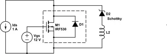
But this neglects that real circuits have inductance. Really what you have is this:

schematic

simulate this circuit – Schematic created using CircuitLab

(CircuitLab doesn't seem to have the appropriate Schottky symbol)

Now say we set \$V_{GS} = 0V\$. The current \$I_{DS}\$ that was flowing in the channel now must find another path. It can go through the body diode, D1, or through the Schottky, D2. The path through D1 has a very small inductance, because the current path need move some microscopic distance. However, D2 is maybe some millimeters away, which has, even with the smallest SMT parts, many orders of magnitude more inductance.

Thus, at least for some brief period after the MOSFET channel closes, current will go through the body diode. The additional inductance (L2) puts a limit on how fast current through D2 can rise, and since the voltage across L2 is clamped to the forward voltage of D1, less the forward voltage of D2, current can't rise all that fast.

Sure, L2 isn't all that big, and you don't have to wait that long. But the whole point of this synchronous rectification is to avoid conducting through either of these diodes at all, so naturally you are going to make this time as short as you possibly can. In light of this, does adding D2 really do anything?

Is there a procedure to find a small yet safe dead time for the complementary PWMs?

I don't think there's any magic method. Measure accurately with a scope, and read datasheets carefully. Depending on what sort of gate driver you are using, maybe there are things you can do to make the gate switching delay smaller and more predictable. For example, if there are common-emitter BJTs in your gate driver, then you can use a Baker clamp. It's also common to design gate drivers to sink more current than they can source, so that turn-off is faster than turn-on. Or, you can measure the storage delay accurately, and compensate in software.

You can also do things to limit the shoot-through current, including a resistance or small inductance in the path, for example. However, this works only to a point, since by introducing such a thing you are also introducing an additional loss.

Phil Frost
  • 56,804
  • 17
  • 141
  • 262
  • thanks for the insight Phil. very interesting. my concern with the body diode was the duration of its rise time, which was about the same as the dead time I was implementing... Good ideas on the dead time. cheers! – mik Jan 18 '14 at 01:39
1
  1. Your assertion is correct - the low-side switching loss isn't exactly zero, but is ignored since during commutation \$V_{DS}\$ is clamped to a diode drop by either the internal diode or the external Schottky. Conduction loss is dominant in the low-side. An external Schottky doesn't pose any problems (so long as it's rated for the task) and is a normal part of a typical synchronous buck design. Quite often it's omitted as a cost savings measure (having the small additional loss in the MOSFET isn't a huge penalty).

  2. Iteratively via measurement is usually the way to go, if the controller has adjustable dead-time. Many controllers have automatic dead-time adjustment these days (with a fixed minimum dead-time), but if yours doesn't, it's best to use a scope and test-measure-adjust until you get a satisfactory result. The datasheet switching parameters are often typical and are only valid at certain operating points, leaving you to judge what's necessary and how much margin to allow for.

Adam Lawrence
  • 32,921
  • 3
  • 58
  • 110
  • thanks mad man. I think I got the reason for the lack of switching losses. thanks! the dead time is set by hand. I think I was cutting it pretty thin. after all, a few ns more wont kill anyone... cheers! – mik Jan 18 '14 at 01:41