1

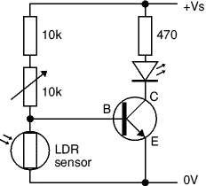
I'm a terribe novice when it comes to electronics and I've got a question: I have a simple circuit including a photocell that regulates current (I hope this terminology is correct). It works as it should: The more light, the more current flows.

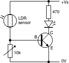
Now I am looking for some opposite device: A schematic / device / photocell (?) that increases its resistance the more light is applied.

Is there something like that? I'd be gracious for any help.

edit details:

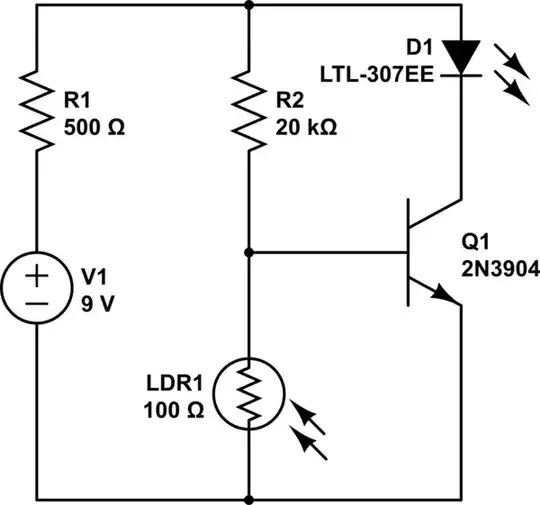
I'm quite sure that what I'm doing is a total no-go, but somehow it's working anyhow (i'd be glad for any tip you guys have :)).. My super-simple (dangerous?) circuit consists of a 9V battery and a power-led. in between their connection I simply placed a photocell. As mentioned, I'd like this photocell to work in opposite of its current function: Power-led should become brighter if I "close up" the photocell.

thanks a ton so far!

benniy
  • 21
  • 5
  • 1
    It's worth adding more details on what you have and the end result you want to achieve. There are a lot of options with light detection so maybe just describe what you'd like the circuit to do if you're unsure of the terminology. – PeterJ Jan 14 '14 at 11:14
  • You might want to connect your photocell in parallel with your circuit... More the light, Less Resistance and more current will flow through photocell branch than your circuit! Or look at: http://www.buildcircuit.com/ldr-engineer/ – Swanand Jan 14 '14 at 11:40
  • You can refer to [this reply](http://electronics.stackexchange.com/a/95967/33841). Also please capitalize "I" [Why should the first person pronoun 'I' always be capitalized?](http://english.stackexchange.com/questions/7986/why-should-the-first-person-pronoun-i-always-be-capitalized) – alexan_e Jan 14 '14 at 11:50
  • thanks guys.. I've added some details & corrected the spelling :) – benniy Jan 14 '14 at 11:58
  • Note that when you edit or create a question in http://electronics.stackexchange.com you can click in the little circuit button to add a circuit, and also it let you simulate it! – PhoneixS Jan 14 '14 at 16:27

2 Answers2

4

Usually you use a photocell

  • to measure light or
  • to switch something on or off

For the latter, a normal photocell can be used for either purpose. If you want to switch something off or on when light falls below a certain level or when light rises above a certain level.

You don't need a different sensor, just use it in a slightly different circuit.

Compare

enter image description here enter image description here
LED lights when the LDR is dark      LED lights when the LDR is bright
From Electronics Club / Transistor Circuits

RedGrittyBrick
  • 14,602
  • 5
  • 37
  • 77
  • Thank you very much for your help! I have added some details above. Do you think your second circuit could work? – benniy Jan 14 '14 at 12:03
  • @benni: No, I'd use a LDR to control a PWM circuit if you want a LED's brightness to vary proportionally to ambient light. – RedGrittyBrick Jan 14 '14 at 12:07
  • thank you.. I'm really helpless :0 .. does [this](http://imagizer.imageshack.us/v2/800x600q90/835/mcd5.jpg) sketch make any sense? > – benniy Jan 14 '14 at 13:06
  • @bennniii: Add a current limiting resistor right next to the LED. (9v - 2v) / 10 mA = 700 so say 680 ohms. It will switch on and off, to achieve a gradual dimming/brightening you need a different circuit. Try with a small 9V incandescent torch bulb instead of resistor+LED. P.S. your diagram uses the symbol for a photodiode but I assume you mean an LDR. – RedGrittyBrick Jan 14 '14 at 13:13
  • great :) .. thanks again & again. is [this](http://imagizer.imageshack.us/v2/800x600q90/713/el4w.jpg) correct now? and, furthermore: i'm kind of dependent on the light being an very bright LED.. will this work the way i painted it? – benniy Jan 14 '14 at 14:50
  • @bennniii: That will be OK so long as you choose the value of the resistor to match the forward-voltage and typical-current in the LED's data sheet (see 2V/10mA example calculation in earlier comment). It's worth adding another resistor below the variable resistor to prevent accidental short-circuiting the 9V power (e.g. when turn variable-resistor to zero + bright light on LDR) – RedGrittyBrick Jan 14 '14 at 15:46
  • ok, i'm getting there. i have three small questions left and i'll stop bugging you: 1) what kind of transistor shall i use? 2) where do the values 9v, 2v and 10mA come from? (9v is obvious, i guess :)) 3) let's say i'd like to connect 3 powerleds that each run on 3v (dont know if this is realistic). do i just hook them up in line? led -> led -> led -> transistor ? – benniy Jan 14 '14 at 17:08
  • 1) NPN with Icmax >> Iled. 2) Typical 5mm indicator LED. 3) Yes if Vsupply is > 3xVled. – RedGrittyBrick Jan 14 '14 at 17:25
0

I think using it in parallel and/or using a transistor can make it work as if it was inverted.

schematic

simulate this circuit – Schematic created using CircuitLab

Where R1 is for secure all the circuit.

For parallel you can think something like this:

schematic

simulate this circuit

Please note that values are more or less random, so they could be insecure.

PhoneixS
  • 223
  • 1
  • 3
  • 9
  • I've added some details. I hope that helps. As for my circuit (now mentioned above): would it work to use the photocells in parallel? And does 'in parallel' mean, I simply use two of them? I'm sorry for my poor knowledge. – benniy Jan 14 '14 at 11:58