1

I'm looking to power multiple robots off a single 230V mains supply in parallel.

I'm using the Micro Magician V2. I can't find out how many amps it draws anywhere but I know the motors I'm using have a stall current of 760mA so I'd guess around 1A per robot?

I will be using 4 robots with this setup

The Micro Magician states it has a:

Built in LDO +5V, 1A regulator (input voltage must be at least 5.5V) to power external 5V devices

Built in LDO +3.3V, 500mA regulator

Does this mean I can have a power supply grid with any amount of amps and the micro controller will protect the board by limiting the amps? The voltage will be around 6V in this grid once I choose an appropriate transformer.

Once I know what amps the power supply grid will need to produce to handle powering the 4 robots I can then choose a transformer?

Let me know if any of the above statements are wrong, I'm quite new to this.

Thank you!

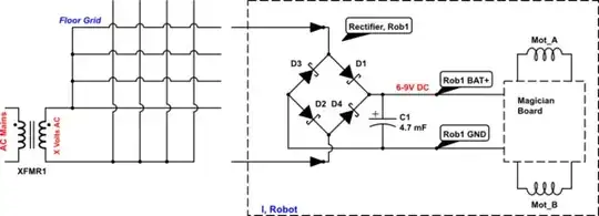
Edit: if anyone is confused about the "power grid" part, I have prototyped this circuit and it works well: Help with a full bridge three phase rectifier powered floor

Titan
  • 189
  • 1
  • 6
  • Ah very useful thank you, so it doesn't matter how high the amp rating of the transformer is, it will only supply what is required (as long as the rating is high enough for 4 robots to draw enough for themselves at the same time) – Titan Jan 14 '14 at 12:12
  • Yes, as Olin analogy describes `If Johnny wants to eat two apples, he's only going to eat two whether you put 2, 3, 5, or 20 apples on the table` – alexan_e Jan 14 '14 at 13:17

1 Answers1

1

From the textual description, this seems to be the configuration planned:

schematic

simulate this circuit – Schematic created using CircuitLab

The Magician controller documentation states:

Built in dual FET "H" bridge with current limiting ...

... each output has been internally limited to 910mA to prevent damage from accidental short circuits.

So the motor driving FETs provide the required current limiting and short-circuit protection on the motor side, nothing additional needs to be done.

Current Calculation:

The above tells us that no matter which DC motors are used, the maximum current in worst-case conditions would be of the order of 2 Amperes per robot with 2 motors, both stalled.

In order to provide for 3 robots, the floor grid must thus be able to supply up to 6 Amperes. Add a bit for headroom, say 8 Amperes total.

Voltage calculation:

The Magician boards suggest that supply voltage should be greater than 5.5 Volts, and not more than 9 Volts. The bridge rectifier output will need to be smoothed by capacitors, to achieve the desired 6 to 9 Volt DC.

A mains-to-6 Volt transformer will provide a peak DC voltage of 6 * 1.4142 = ~8.5 Volts minus 2x diode drop, so say around 7.5 Volts. (Transformers are rated at their RMS voltage. Peak voltage is obtained by multiplying by sqrt(2))

This is comfortably within the desired operating range, so you're all set, other than increasing the reservoir capacitor C1 until the system works reliably, and then adding a few thousand microfarads on top. The 4700 uF indicated in the diagram will possibly be too low at full motor load, leading to unacceptable ripple on the supply line - start with 4700, keep increasing this if the controller resets on acceleration or stall.

Anindo Ghosh
  • 50,188
  • 8
  • 103
  • 200
  • Wow thank you for such a detailed response! Firstly, I may not use a capacitor as I originally planned to use a small UPS similar to: http://www.piups.net that would switch to battery power in the event the brushes did not align with the power grid. On that note, it's been suggested by a couple of people to do a chess board style grid but I was intending to have just parallel strips in my original question: http://electronics.stackexchange.com/questions/93886/creating-a-small-scale-bumper-car-ground-power-grid – Titan Jan 14 '14 at 18:55