3

I have 8pin 4x4 keyapd, and i want to connect it to my microcontroller, I've search over the net but i can't see its pin configuration. I have a problem connecting it because of that can someone help me. I have a picture of the keypad and pin description of my controller here.pi description

enter image description here

NewInEverything
  • 87
  • 1
  • 6
  • 14
  • possible duplicate of [Seeking 4x3 keypad for Atmel UC3 microprocessor](http://electronics.stackexchange.com/questions/95162/seeking-4x3-keypad-for-atmel-uc3-microprocessor) – Ignacio Vazquez-Abrams Jan 13 '14 at 10:17
  • You need connect to any Digital I/O port. – Butzke Jan 13 '14 at 10:17
  • It's not a duplicate question, btw, I have searched what i am looking for over the net. thanks for you answers. – NewInEverything Jan 13 '14 at 10:23
  • You should double-check the results using the techniques in the answers, but it looks to me a lot like the one Parallax and others sell http://www.parallax.com/sites/default/files/downloads/27899-4x4-Matrix-Membrane-Keypad-v1.2.pdf – PeterJ Jan 13 '14 at 10:41
  • See (if you want to use only ONE pin): https://www.youtube.com/watch?v=URO042VrCKU – Codebeat Jul 26 '16 at 13:36

3 Answers3

4

Figuring out the matrix wiring of the 4x4 keypad is dead simple with an ohm meter. Attach the meter leads to selected pairs of the conductors in the connection cable. Then press the buttons one at a time to see which switch closes the connection between the selected conductors. If you write down the connection numbers as 1 to 8 and then make a table of the selected pairs in sequence and which switch closes each pair. Some pairs will not cause any closures to be registered. When this happens you will know that the selected pair of connection wires are either both row wires in the switch matrix or column wires.

Michael Karas
  • 56,889
  • 3
  • 70
  • 138
4

Here is a relevant guide

enter image description here

Keypad Pin  Connects to Arduino Pin...
1           D9
2           D8
3           D7
4           D6
5           D5
6           D4
7           D3
8           D2

enter image description here

/*4x4 Matrix Keypad connected to Arduino
This code prints the key pressed on the keypad to the serial port*/

#include <Keypad.h>

const byte numRows= 4; //number of rows on the keypad
const byte numCols= 4; //number of columns on the keypad

//keymap defines the key pressed according to the row and columns just as appears on the keypad
char keymap[numRows][numCols]=
{
{'1', '2', '3', 'A'},
{'4', '5', '6', 'B'},
{'7', '8', '9', 'C'},
{'*', '0', '#', 'D'}
};

//Code that shows the the keypad connections to the arduino terminals
byte rowPins[numRows] = {9,8,7,6}; //Rows 0 to 3
byte colPins[numCols]= {5,4,3,2}; //Columns 0 to 3

//initializes an instance of the Keypad class
Keypad myKeypad= Keypad(makeKeymap(keymap), rowPins, colPins, numRows, numCols);

void setup()
{
Serial.begin(9600);
}

//If key is pressed, this key is stored in 'keypressed' variable
//If key is not equal to 'NO_KEY', then this key is printed out
//if count=17, then count is reset back to 0 (this means no key is pressed during the whole keypad scan process
void loop()
{
char keypressed = myKeypad.getKey();
if (keypressed != NO_KEY)
{
Serial.print(keypressed);
}
}
alexan_e
  • 11,070
  • 1
  • 28
  • 62
  • this connection is using parallel communication right? Can I have it's output on a lcd using serial communication? – NewInEverything Jan 13 '14 at 10:40
  • @NewInEverything All the pins of the matrix need to be connected in order for the keyboard scan to work properly. The example code just outputs the result using the serial port (to a terminal) but you can modify the code to show the result to a display. – alexan_e Jan 13 '14 at 10:49
  • so I can only see the output in the serial monitor? – NewInEverything Jan 13 '14 at 10:51
  • @NewInEverything Yes, read the comment of the code for the last part – alexan_e Jan 13 '14 at 10:57
  • Ok. D9-D2 is the digital input/output of the aruino right?. Sorry for asking too much, i am really a beginner when it comes to electronics. – NewInEverything Jan 13 '14 at 11:01
  • @NewInEverything For the specific task the pins operate as digital I/O but there are other alternative functions for the same pins, it depends on the mode used. – alexan_e Jan 13 '14 at 11:33
  • How can I throw the value I inputted through the keypad to the arduino as an integer? – NewInEverything Jan 14 '14 at 09:15
  • 1
    @NewInEverything `keypressed` variable contains the read value as a char, after checking that a button has been pressed (`if (keypressed != NO_KEY)`) you can use the value whenever you want, but if you need an integer you have to convert it. For characters "0"-"9" to be converted to integers you just need to subtract decimal 48 (that is 0x30 as hex) – alexan_e Jan 14 '14 at 09:39
  • so you mean that i need to change "Serial.print(keypressed);" to "Serial.print(keypressed - 48);" to convert it to integers? – NewInEverything Jan 14 '14 at 09:55
  • so i tried changing that code into "Serial.print(keypressed - 48);" and i still got the apropriate output, is that mean the output is integer? – NewInEverything Jan 14 '14 at 10:00
  • @NewInEverything, that functions purpose is to send the value to the serial port, why do you want to send the integer value through the serial port? Apart from that the conversion of the char to int is correct (for values 0-9). You originally said "input through the keypad to the arduino", the `keypressed` variable is already in the arduino memory, you don't need to send it anywhere, just process it the way you intend depending on your task. – alexan_e Jan 14 '14 at 10:02
  • well i needed it because I am creating a calculator. thus I have and lcd display connected to the arduino with serial communication, With your code I can also display it to the lcd. that sums it up. – NewInEverything Jan 14 '14 at 10:06
  • if i want to convert the "A" all I need to do is write this code if(keypressed == 2A){Serial.print("+");} right? "2A" is the hex value of "A". – NewInEverything Jan 14 '14 at 10:19
  • @NewInEverything No, that is not the 'A' hex value, you can see it in any [ASCII table](http://upload.wikimedia.org/wikipedia/commons/1/1b/ASCII-Table-wide.svg) it's 0x41. Apart from that your code will send +' when `keypressed` equals 'A' (that is `if(keypressed == 0x41`) or the alternative `if(keypressed == 'A')`) – alexan_e Jan 14 '14 at 10:28
  • I got simplier solution. I just edited the keymap and put "+" instead of "A".haha. Thanks though – NewInEverything Jan 14 '14 at 14:05
  • and you mean `if(keypressed - 48)` rather `if(keypressed == 0x41` because that will return display"0." – NewInEverything Jan 14 '14 at 14:10
  • @NewInEverything This `if(keypressed == 0x41` is the same as `if(keypressed == 'A'`, it will be true when keypressed equals char value 'A'. The -48 trick only has purpose if the intension is to convert characters '0'..'9' to integers 0..9 – alexan_e Jan 14 '14 at 14:21
  • That's what I need to do. To convert it '0'-'9' to integers. BTW, I've got it working only in addition. I'm still figuring what to do next, if i cant work it out. ill ask for your help again – NewInEverything Jan 14 '14 at 14:36
4

I've search over the net but i can't see its pin configuration.

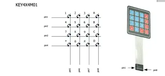
I assume I'm seeing an 8 wire tail.
Maybe 9. Just maybe 7.

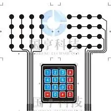
The keypad is likely to have the connections brought out as 4 rows and 4 columns. If there is a 9th wire it may be a shield.

Use an Ohm meter set to say something like 100k (or 199.9k or whatever) range. This allows you to not miss very high resistance contacts. A 20k range MAY be OK but 200k is safer.

Make contact with conductive end of tail with meter probes. Try putting 2 probes on the same tail and ensure you can easily see the meter respond - most tails will be insulated until near the end and some may be oxidised on the conductive surfaces and need a CAREFUL rub with the meter probe tip to make contact. Tails may be made by depositing conductive ink so will usually not be super strong so use reasonable care when making contact. They are usually not super delicate - just be sensible.

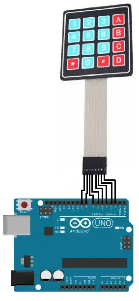
IF you have a connector for the keyboard, use it. I'll assume 8 conductors numbered 1 to 8 below. Adjust as needed.

Having an assistant is not essential but helps.
Hold down one key and place one probe on contact 1 (1st wire) and go along all other wires 2-8 with probe to see if a contact can be found.
If not, place one probe on 2nd wire (contact 2) and go along 3-8. Then
3 + 4-8
4 + 5-8
5 + 6-8
6 + 7-8
7 + 8

If you do not get a contact closure on ANY of the above then you are not making proper contact (most likely) or the keyboard is dead (less likely).

Record the result and try another key.

After a few tries a pattern will appear. Probably 4 x row and 4 x column as above.

An alternative method is to choose two contacts for meter probes and press keys in turn until a closure occurs eg contacts on 2 + 5 MAY respond to key 4. (2nd row, 5-4 = 1 = 1st column) but may not.

This method MUST work if done properly if the matrix has only switches.

SOME keyboards have internal diodes but this is extremely unlikely for your keyboard. For keyboards with diodes, meter polarity matters.


Kayboards that look very like yours can be found at:

Here - see below

enter image description here


And here for $6.99 - same arrangement.
Manufacturer: Parallax
Product Code: Dev-4x4Key-01


Maybe herefor $ less.

Datasheet

enter image description here

Russell McMahon
  • 147,325
  • 18
  • 210
  • 386