I want detect a 220 VAC AC signal using an AVR.
I could convert 220 VAC to 5 VDC with an opto-coupler.
How can I detect the exact time of the signal?
What about blinking signal per half second?
Asked
Active
Viewed 7,448 times
0
Russell McMahon
- 147,325
- 18
- 210
- 386
user31339
- 9
- 1
- 2
-
1Could you please explain what you mean by "real time", as you have mentioned in some comments? Also by "exact time of signal", do you mean the exact frequency of the 220 Volt AC? – Anindo Ghosh Jan 11 '14 at 11:18
-
The meaning of the terms "the exact time of the signal" and "blinking signal per half second" are not clear. Would you please explain these terms in more detail. – Russell McMahon Jan 11 '14 at 11:32
-
Realtime is ? within 1 minute, 1 second, 1 milli second, 1 micro second or other... delete those that do not apply.... – Spoon Jan 11 '14 at 12:49
-
1What is the negative? You want to detect 220VAC versus nothing? Versus 220 DC? Versus 120 AC? Versus 10kHz 1V signal? In other words what are the inputs you are trying to discriminate? – angelatlarge Jan 11 '14 at 22:08
3 Answers
3
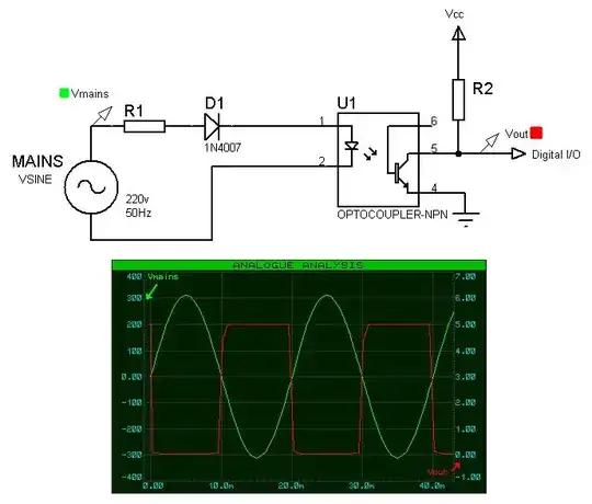
Assuming I get the requirement correctly you can use the following:
An optocoupler that outputs pulses to a digital pin for each zero cross of the mains voltage, you'll get 100 pulses for a 50Hz input frequency.
If you want to get the pulses only when the mains is above a specified level (for under-voltage detection) then you can use a zener in the opto diode side to introduce a voltage drop.
In the following example the zener used is 1N5281 which is a 200v diode, so in order turn on the optodiode the mains voltage need to raise above Vzener + Vfdiode + Vfoptodiode which results to about 203v.
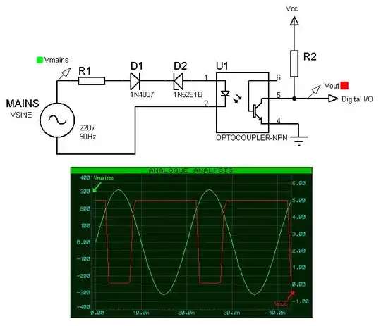
Both these circuit offer the benefit of mains isolation.
The schematics have been update, the resistor values should be calculated per case. In both graphs the green trace is the mains input (left axis) and the red trace the output (right axis).
As jippie noted, care must be taken regarding the power dissipated on R1 and possibly replace it with two resistors in needed in order to operate them within voltage specs.
As Anindo Ghosh noted, the resistor value R1 needs to be selected based on the current transfer ratio of the used optocoupler and the output current requirement.
As JoeHass noted, in one of my previous circuits the diode was connected anti-parallel to the opto-diode which resulted in increased dissipation on R1. The diode has been moved in series with the opto-diode so that the current through R1 flows only for half cycle (in one polarity).
alexan_e
- 11,070
- 1
- 28
- 62
-
i use this circuit but i serch for a metod to detect signal real time si – user31339 Jan 11 '14 at 09:56
-
2@user31339 And why isn't an optocoupler real time ? I'm not sure I get what you mean. – alexan_e Jan 11 '14 at 09:56
-
2Notice that the 22k resistor in your circuit is dissipating 2.5W and many resistors are not rated for 230 V(AC) or more. – jippie Jan 11 '14 at 10:52
-
1@jippie Actually the 22K resistor will drive the opto-led with about 10mA which is high for the output requirement (of driving a digital input). A 100K - 220K resistor would provide more that enough current (1-2mA) with a low power dissipation (0.5W or less). – alexan_e Jan 11 '14 at 11:42
-
@alexan_e Still a lot of power for a resistor without annotations. And 0.5W resistors too are rarely rated for 230V(AC). Most low power resistors are rated for 200V(DC), so two in series would do the job both voltage and powerwise, but it is worth to check the datasheet. – jippie Jan 11 '14 at 12:49
-
@alexan_e That does depend on which optocoupler is used, as CTR varies with LED current: The [4n35](http://www.vishay.com/docs/81181/4n35.pdf) for instance has a typical CTR of around 0.25 at 1 mA LED current - See figures 2, 3 etc. A collector current of 250 uA would bring output close to or below the noise floor in typical applications. – Anindo Ghosh Jan 11 '14 at 13:01
-
Wouldn't it be better to put the IN4007 in series with R1 in the first figure, as you did in the second figure but without the zener, to cut the power dissipation in the resistor in half? And I agree with @jippie that care needs to be used in selecting and using said resistor. – Joe Hass Jan 11 '14 at 13:01
-
@jippie maybe it is better to remove the values from the schematic and add a note in the text. – alexan_e Jan 11 '14 at 13:22
-
@JoeHass That is correct, I have made these schematics a long time ago and attached them as they were, that is why the first one has the diode anti-parallel to the opto diode and the second one the diode in series where it lowers the dissipation on the resistor by half. – alexan_e Jan 11 '14 at 13:25
-
1I like the anti-parallel diode anyway, LEDs are not very good with reverse bias. I realize that is the reason for the series diode, but I like the anti-parallel (or both) better to relieve the stress from the LED. Also I would probably replace the resistor with a (X-rated) capacitor, in series with a small (100 - 1kohm) resistor. – jippie Jan 11 '14 at 21:42
-
@jippie How is the opto-diode going to be stressed with reverse bias when there is a diode in series that prevents this? I'm obviously missing something. Other than that it is very simple to add the anti parallel diode and the additional cost will be negligible. Regarding the capacitor, I've seen it used in transformerless power supply app notes but I haven't used it so I'm not confident to use this way in the posted schematic. – alexan_e Jan 11 '14 at 22:11
-
2I expect the series diode and LED will act as a more or less evenly distributed voltage divider. If both are equivalent to about 100Mohm, then there will still be an unacceptable voltage build up across the LED. – jippie Jan 11 '14 at 22:14
2
\$C = \dfrac{I}{2\pi f U} = \dfrac{10\text{mA}}{2\pi \cdot 50 \cdot 230} = 138 \text{nF} \Rightarrow 100\text{nF}\$
simulate this circuit – Schematic created using CircuitLab
- Assumed 50Hz mains frequecy.
- Chose 10mA to safely compensate for VRMS / VPK = √2, and under assumption of 20mA maximum current for the LED in the optocoupler.
- R1/R2 to discharge the capacitor when the device gets unplugged. Two resistors because most low power resistors are rated for 200V(DC) max.
- D1 to ensure C1 can (dis)charge every half cycle and to protect LED D2 against being reverse biased.
- R3 to protect against inrush current and low power resistor will blow when C1 fails short.
jippie
- 33,033
- 16
- 93
- 160
-
Note that the capacitor introduces a phase shift by \$ 90^o \$ which results to output pulse transitions at the (positive/negative) peaks of the input sine wave. – alexan_e Jan 12 '14 at 01:29
-
I personally prefer to tap the AC voltage from a transformer rather than directly from mains. – jippie Jan 12 '14 at 09:03
-
Yes that is a good idea but the transformer is not always accessible, for example when a sealed wall wart is used or a battery supply or USB supply etc. – alexan_e Jan 12 '14 at 11:09
0
Atmel application note AVR182 gives an implementation of a zero crossing detector. Note very carefully the following on page 2:
It should be noted that this solution will not give any galvanic isolation for the microcontroller against the AC mains.
This means that you must take appropriate precautions before attempting to use the solution.
Ignacio Vazquez-Abrams
- 48,282
- 4
- 73
- 102