Update based on the use of the CDC (photocell) input already on the board (as discovered by the OP)
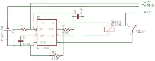
The schematic of the PIR board you refer to is similar to the following

It shows that the CDS pads (Cds2 in the schematic) connects to pin 9 of BISS0001
According to the datsheet that pin is:
Trigger disable input (VC)
VC >0.2Vdd=enable
VC<0.2Vdd =disabled)
Vdd supplied to the chip is 3.3v (from the 3.3v onboard regulator) so if you apply voltage >0.66v to that pin the controller turns on, if you apply <0.66v then it turns off.
One of the CDS pins is already connected to ground,the other one is connected in series with an onboard resistor of 1M Ohm to the 3.3v supply.
The CDC and the resistor form a voltage divider, if the CDS sensor has a resistance of 250K or higher the controller will turn on, if it has <250K then the controller will turn off.
You just need to find an appropriate CDS or add an external resistor to adjust the switching point.
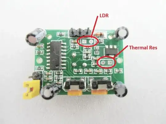
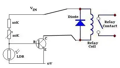
The LDR (Light Dependent Resistor) has a resistance which increases in darkens and decreases with light.
Using that property you can connect it in a voltage divider to drive the base of a NPN transistor and turn on/off a load based on the room brightness.
Such a circuit that turns on at darkness looks like
If you are looking for the opposite effect you can use
Note that Vin is the positive supply line
You can replace the 500 Ohm resistor and led of the above circuits with a relay that replaces your switch.
Images from http://www.reuk.co.uk/Light-Dependent-Resistor.htm