Balanced audio has the signal on one conductor, and the inverted signal on another conductor.
WRONG.
Balanced audio has two signal conductors, and a third for ground.
WRONG.
Either of these things may be true, but neither is what makes balanced audio. Telephone networks until fairly recently were entirely analog, and had only two wires per circuit. There was no ground. Yet, they managed to maintain a relatively noise-free connection over very long distances. Only two conductors are required for balanced audio.
An ideal balanced audio receiver is a differential amplifier. It works by measuring the difference between its two inputs, and calling that difference the signal. "Ground" is totally irrelevant. One input need not be an inverted copy of the other input. How could it matter, if a differential amplifier is only looking at the difference between its two inputs? How could it know that one input is "the inverted signal"?
Why then, not simply connect one of the inputs to ground? Wouldn't this mean we can make any unbalanced audio into balanced audio just by using a differential amplifier on the receiving end?
simulate this circuit – Schematic created using CircuitLab
As it happens, no, we can't do that, and to understand why is to understand what balanced audio really means. It's not about having two single-ended audio connections, but with one inverted. It's about having the signal be carried on two conductors with equal impedance.
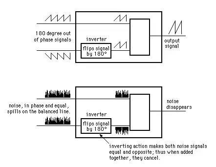
Here's why: the primary objective in using balanced audio is to reduce noise. This noise is picked up by mutual inductance and capacitance with other stuff (frequently: mains wiring) near the audio signal. If the mutual inductance or capacitance to this noise source is equal for our two conductors, then equal voltages and currents will be induced on each conductor. That is, their difference will not change. Thus the noise source, from the perspective of our differential amplifier which only looks at this difference, doesn't exist. Consider:
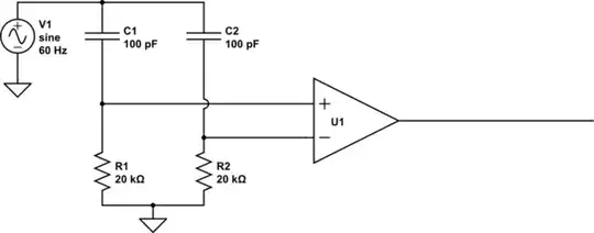
simulate this circuit
What's the output here? To the extent that U1 is an ideal differential amplifier, the output is exactly 0V DC. Some of the noise (from V1) couples into the inputs through C1 and C2, but because C1=C2, and R1=R2, it couples into each equally, and thus can't change the difference between the two, so can't affect the output of the differential amplifier.
But what happens if R1 is not equal to R2? R1 and C1 now form a different voltage divider than do R2 and C2, resulting in unequal voltages coupling into the amplifier's inputs. Now there is a difference, and V1, to some extent, is found in the output. The same problem exists if the resistors are equal but the capacitors are not.
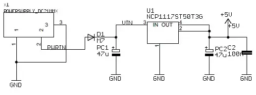
Driving just one of the inputs doesn't change anything. Consider:
simulate this circuit
Hey that's not balanced! But it totally is balanced. The noise still sees equal impedances to each of the inputs. The noise still couples equally into each input, thus not changing the difference. Thus, it's still rejected.
There are two reasons your typical audio connection such as found on an iPod or a VCR isn't balanced. The first is the cable geometry. Usually these use coaxial cables, with the ground as the shield, and a ground-referenced signal inside of it. Because the shape of the conductors isn't even remotely similar, they can't possibly have equal impedance to their surroundings. In terms of the prior examples, C1 and C2 are not equal.
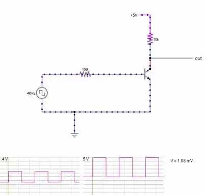
The second is how these lines are typically driven. They usually look something like this:
simulate this circuit
If U1 were an ideal buffer, this would be balanced. But it's not: U1 is usually some sort of op-amp with a small output impedance. Though it is small, it's not nearly as small as the direct connection to ground seen by the other half of the cable. The op-amp's output impedance probably also varies significantly with frequency.
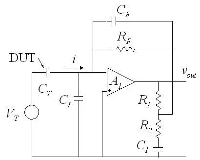
A very cheap, and very effective solution to this problem is to set the output impedance with something more controllable, like a resistor. We can put a resistor on the order of 100 ohms in series without significantly attenuating the signal. A practical implementation looks like this:
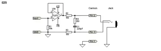
This is from a great article by Rod Elliott (ESP) / Uwe Beis. R2 and R3 do most of the balancing: these resistors can be purchased or trimmed to have very equal resistances. Since they are significantly bigger than the output impedance of the op-amp, the op-amp's output impedance is relatively insignificant.
R4 and C1 serve to further render the op-amp insignificant at higher frequencies. Real op-amps have increasing output impedance with frequency, which would serve to unbalance the circuit at high frequency. However, the op-amp's output impedance becomes less significant at higher frequencies as R4 and C1 shunt the two halves together.
This topology is not without a few disadvantages. Firstly, since it can't drive both lines, it has half the dynamic range compared to a design that can drive both lines. Secondly, it drives the two signal lines with a common-mode voltage half that of the input signal. The driver must thus drive the capacitance of the two signal lines to their surroundings, like the shield in typical audio cables. However, for moderate cable lengths this is unlikely a problem.
The advantage is reduced parts count. Also, if this is on a TRS connector which gets shoved into an unbalanced input, nothing bad can happen, since the ring, which is normally "inverted signal", isn't connected to any active electronics.
More importantly, it dispels a common misunderstanding about how balanced audio works.