7

I'm using TI Tiva C TM4C123GH6PM on a Launchpad combined with an AD 9850 DDS to create frequency modulator.

Currently I have an extremely simple program which basically sets up microcontroller's peripherals and the AD9850 and then goes into a loop in which it samples audio signal coming to the microcontroller's ADC and based on the results adjusts the output frequency of the DDS.

My problem is that the loop's execution time is not constant.

The loop is divided into three basic parts: In the first part, I get a sample from the ADC, in the second part, the required settings for the AD9850 are calculated and in the third part those settings are sent to the AD9850.

After doing some cycle counting, it turns out that the second and third part always last for 2670 clock cycles. This leaves me with the only suspect being the first part.

After measuring the execution time of the first part just by itself, I've noticed that it varies from as low as 100 cycles to as much as 8000 cycles.

Here's a nice graph I got from the debugger showing how the number of cycles changes with time:
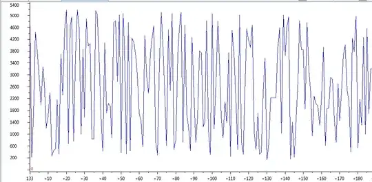
Graph showing on its Y axis number of cycles it took for the ADC to provide a sample and on its X axis number of samples taken

I did look into the datasheet of the part and into the Tivaware Peripheral Driver Library User's guide and I couldn't find a reason why the sampling would have such drastic jitter. The ADC sampling plus conversion time is listed as 1 microsecond, which is around 80 processor cycles, since I'm running at 80 MHz clock frequency. This makes the loop duration in the area of around 100 to 200 cycles look OK, but I have absolutely no idea what's happening in the case when the time is in the thousands of cycles.

I have also read the errata for the ADC and as far as I can see, none of the numerous problems apply to my case. Also the part I have is an actual TM4 part, not an experimental XM4 part.

Here's the problematic part of the code:

c_start = HWREG(DWT_BASE + DWT_O_CYCCNT); // starts cycle counting
ROM_ADCIntClear(ADC0_BASE, 3);//clears interrupt flag
ADCProcessorTrigger(ADC0_BASE, 1);//Triggering sequence 1
while(!ROM_ADCIntStatus(ADC0_BASE, 3, false))//Waits for ADC to finish converting
{//Busy wait to be replaced with an ISR at some point
}
ROM_ADCSequenceDataGet(ADC0_BASE, 3, adcData);//adcData pointer to memory location 
//used to store results
c_stop = HWREG(DWT_BASE + DWT_O_CYCCNT); // Ends cycle count
c_dur=c_stop-c_start;//Provides number of cycles, refresh breakpoint goes here

Here's the ADC setup code:

ROM_SysCtlPeripheralEnable(SYSCTL_PERIPH_ADC0);//Pin is PD1=>channel AIN6
ROM_ADCHardwareOversampleConfigure(ADC0_BASE, 64);
//Averages 64 samples and stores them in one FIFO slot,
//has apparently no effect on the conversion time, same results when disabled

HWREG(ADC0_BASE+ 0x038) = 0x40;//This enables hardware dithering


ADCSequenceConfigure(ADC0_BASE,3,ADC_TRIGGER_PROCESSOR,0);
//Uses ADC0, sequence 3=>FIFO with length of one, highest prioroty
ADCSequenceStepConfigure(ADC0_BASE,3,0,ADC_CTL_CH6|ADC_CTL_IE|ADC_CTL_END);
//First and last step, selects ADC0, sequence 3, step zero, channel 6,
// enables interrupt and ends sequence
ADCSequenceEnable(ADC0_BASE,3);
//Enables sequence

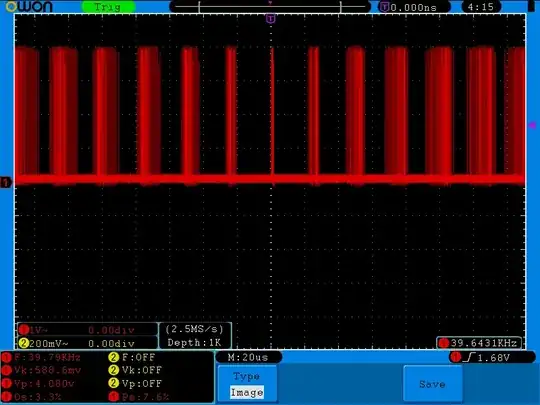
UPDATE: I went ahead and did the test with pin wiggling and I got relatively similar results. On this image, a pin goes high and then immediately low as soon as ADC is done. This is taken with dithering and hardware oversampling disabled, with sample rate of 1 MSa/s and FIFO buffer depth of 1. enter image description here
AndrejaKo
  • 23,261
  • 25
  • 110
  • 186
  • 1
    Doubt if it's causing the problem but I think to enable dithering the syntax should be more like `HWREG(ADC0_BASE+ 0x038) = 0x40`. Also I wonder in case it's a problem with the DWT unit setup if you haven't done anything similar already it might be worth toggling an I/O and measure with a scope to take that out of the equation. – PeterJ Jan 04 '14 at 12:13
  • @PeterJ I myself am not sure about the syntax... Also what's DWT? I can wiggle pins with HWREG, but even using that, the time it takes for pin to go low after being set high is very long. – AndrejaKo Jan 04 '14 at 12:51
  • OK, DWT seems to be Data Watchpoint and Trace and is mentioned in the datasheet. – AndrejaKo Jan 04 '14 at 19:33
  • @PeterJ I did some testing and you were right about the dither bit setup. Thanks a lot for catching that bug! – AndrejaKo Jan 04 '14 at 20:43
  • 2
    This isn't an answer, but the workaround is simple. Arm the ADC *after* checking for a result rather than before. If no result is ready when you check, re-use the previous one. There's no reason to wait for the ADC -- let it work on getting the next sample while you're processing the previous one. – David Schwartz Jan 05 '14 at 08:15
  • When my code seems to be irregularly taking a lot longer than I expected, it's usually because of interrupts. Sometimes I don't have a proper interrupt handler, and when that interrupt is triggered it executes random code. Sometimes I put too much code inside one interrupt. Sometimes my software is just fine, but hardware generates interrupts faster than anyone expected -- [interrupt storm](https://en.wikipedia.org/wiki/interrupt_storm). Could you do a quick test with all interrupts temporarily disabled? – davidcary Jan 06 '14 at 12:15
  • @davidcary Actually, in my case, all interrupts are disabled and all ISRs are the default `while(1){}`. I am using the interrupts flag to determine if the ADC is done, but I'm just polling it. The interrupt itself is disabled. – AndrejaKo Jan 06 '14 at 13:28
  • I bet PeterJ meant WDT that stands for watchdog timer. If it is enabled a counter is incremented at each clock cycle, if the counter overflows the micro is reset, so the programmer should reset the counter every now and then to avoid that. The idea is: my code fails, the micro locks but in a few ms it is reset by the wdt. Check this also. – Vladimir Cravero Jan 07 '14 at 20:16
  • @Vladimir Cravero Do note that no `WDT` unit was mentioned so far. Furthermore, I'm well aware of what watchdog timer is and in this case it's not helpful. There is too little code of for it to be stalling in unknown locations and there's no advantage of resetting the micro instead of having it hang. If it hangs, I can easily see exactly where it is using a debugger, but if it gets reset, then I lost that important piece of information. – AndrejaKo Jan 07 '14 at 20:42
  • @AndrejaKo if the wdt is enabled and you do not reset it it does not matter how much code you are running, the micro will eventually be reset by the wdt. The wdt register is 32bit wide and should fill in more than 53s, the wdt should be off on reset, but the behaviour you're experiencing is quite similar to a bad wdt... – Vladimir Cravero Jan 08 '14 at 22:00
  • @Vladimir Cravero But I never enabled clock for the watchdog timers at all! When this happens, the microcontroller does not reset itself. If it did, I would see that in the debugger. I absolutely never enabled watchdog timers on this microcontroller. – AndrejaKo Jan 08 '14 at 22:13
  • Yeah, that's what I realized too after checking in the datasheet. You know, it was just to be extra sure. – Vladimir Cravero Jan 09 '14 at 23:16
  • @Vladimir Cravero Yeah, I agree that it's best to be extra sure and check then to just write it off. I did check the status of it in the debugger just in case something unexpected is going on. – AndrejaKo Jan 09 '14 at 23:40
  • @AndrejaKo what is the frequency of the ADC clock and is it synchronous with the TM4 clock? Your plot make me think that the ADC clock is much slower and not synchronized with the TM4 hence the noise pattern, but I might be wrong. – vrleboss Mar 04 '14 at 20:22
  • @vrleboss That's a very good comment!The clock for the microcontroller is derived from the 16 MHz crystal whose waveform goes into a PLL and is then divided by 2.5. The datasheet says following for the ADC clock:`Most of the ADC control logic runs at the ADC clock rate of 16 MHz. The internal ADC divider is configured for 16-MHz operation automatically by hardware when the system XTAL is selected with the PLL.`, so in my opinion, since both clocks are derived from the same PLL, they should bee synchronized, with ADC clock period taking 5 main clock periods. – AndrejaKo Mar 08 '14 at 12:52
  • @vrleboss It's also possible to derive the ADC clock from the PIOSC and directly from the MOSC so it may be worth checking if the clock could somehow be coming from there. – AndrejaKo Mar 08 '14 at 12:55
  • When you measured the jitter in conversion time, what was the analog input at? Is it held at a known voltage, or is it varying? It's a long-shot, but I wonder if the voltage being read has an impact. Depending on the ADC method, it's common to see a variation in time to complete a read based on the input level; particularly in successive approximation ADCs which are common in MCUs. – Oliver May 15 '14 at 14:18
  • Just wondering, does your signal source have a constant impedance (more or less) across all freq.? – user34920 Jul 02 '14 at 09:22
  • @user34920 Well my signal is a random-length wire antenna, so I guess that it does not have constant impedance. – AndrejaKo Jul 02 '14 at 11:02
  • Does conversion time vary w/ value being read? Is it constant (or close) if converting a constant value? – Scott Seidman Oct 09 '14 at 14:02

5 Answers5

4

While there are reasons described by others concerning where your jitter may be coming from, being dependent upon things like conversion time (or even hidden branches in function libraries where each branch takes different times) is just poor practice for real time systems.

If you need low jitter loop time, you need to MAKE IT by creating a timer interrupt to give it to you. If you need speed, the timer should be set at your maximum time through your loops, plus a bit of head room. On a timer interrupt you should service everything that needs to be done based on your last ADC read, then do the next ADC read.

Scott Seidman
  • 29,274
  • 4
  • 44
  • 109
2

When this happens, the microcontroller does not reset itself. If it did, I would see that in the debugger.

I suspect that you are always running this under the debugger and you have set a watch on adcData because it's interesting data. The IDE is helpfully preserving that between runs. I will further guess that the TI processor supports hardware watchpoints on memory writes, and the debugger is using those to catch updates to adcData. Each time through your loop the debugger hits the watchpoint and stops for as long as it takes for the external debugger to read out the data and resume the chip.

If you kept the bit wiggling and ran without the debugger you could test this theory.

Ben Jackson
  • 789
  • 3
  • 13
2

As a sidenote, the ADC acquisition time is supposed to be finite, but I have seen some variance in characterizing components. The datasheet likely gives a typical or a "guaranteed by design". Also, the validity of each aquisition isn't guaranteed due to noise, either from layout or otherwise.

Whistle1560
  • 391
  • 2
  • 5
2

You don't mention interrupts, but I see that you're clearing an interrupt flag in the code. If you haven't yet, try disabling interrupts globally. If any other interrupts are going off, they may be causing this jitter.

With a software-based loop, there are lots of things that can cause irregular execution. The most reliable way to get precisely sampled data is to trigger the ADC using a reliable source like a timer (which I believe you can do with no external hardware on this device). The same timer signal could trigger an ISR, where you can collect and use the result at greater leisure, or it could trigger DMA to copy samples into a buffer of some sort.

I suggest caution with libraries like TivaWare. They are usually written for convenience, not high efficiency. If you can track down the source code, you will probably find that they are doing a remarkable amount of housekeeping in those routines. Very often you will get much better performance by hitting the registers directly.

MPA
  • 41
  • 2
2

There are 3 most used types of analog to digital converters.

  • Counter type ADC.
  • Successive approximation type ADC.
  • Flash type ADC.

    1. Counter type ADC:

      In this type the input is compared with a reference voltage digitally generated.the reference voltage is increased step by step til the reference voltage is greater than input voltage.So for different input voltages the time take for conversion is different.

    2. Successive approximation type ADC:

      In this type the same principle is used but in a smart manner. first input voltage is compared with Va/2 (where Va is the upper limit of input voltage) to find in which half it lies . if it is greater than Va/2 its is compared with 3Va/4 else it is compared with Va/4 to find in which quarter it lies.Something like a binary search in computer programs.

    3. Flash type ADC:

      In this type the input voltage is compared with all the voltage levels at the same time and corresponding output is given . The time taken in this type of conversion is constant and does not depend upon the input voltage.

For more info on ADC read pdf: http://www.physics.arizona.edu/~haar/ADV_LAB/ADC.pdf

I suggest a Flash ADC would be best for your circuit. If you want work on the same hardware there are two thing you could do.

  1. find the maximum time (Ta) the ADC takes for conversion . Set a timer interrupt to any value more than Ta. Each time you request a conversion start the timer, and execute the rest of the code only after the interrupt has occurred . this is not the best way but you will get ADC conversion in a constant time. code structure will look something like this:

    • (part 1):
    • Request for conversion.
    • Set up timer interrupt.
    • i=0;
    • while (i==0){} //no need of polling
    • store data from ADC
    • execute part 2 and part 3 same as before

      Interrupt service routine for timer interrupt

      • {i=1;}

    Note:set up timer interrupt means set the timer to 0 and enable interrupts.

OR

  1. use the ADC in free running mode (ADC keeps converting no matter a conversion is requested or not). Each time you want to take a sample ,just load it without requesting for ADC conversion . no need of while loop. (But for this method to be used your ADC must support free running mode)
Tanmay
  • 31
  • 4
  • I am new to stack exchange and so not used to this type of formatting. anyways Thank you. Hope its more readable now. – Tanmay Oct 09 '14 at 15:28
  • Comprehensive answer. There are a number of different sorts of ADCs that might fall into your "counter" type, such as integrating ADCs; slope, dual slope, and the like, where the comparison voltage is a constant, but a counter rolls while the integrated signal is dumping. – Scott Seidman Oct 09 '14 at 16:47