0

I have a microcontroller and a small video/still "spy" camera (like these) that came in a case disguising it as a car remote. The microcontroller is a TI MSP430 value line model, though I could use an ATMEGA/ATTINY via arduino if the MSP430 doesn't work out.

I have the two devices sharing a ground, but each is powered by separate batteries because the camera wants about 4.7v and the MSP430 runs on 3.3v.

I'm trying to use a pair of transistors to act as the Power and Function buttons on the camera, in order to use it as a time lapse controlled camera. I removed the push buttons on the camera's board and wired the contacts up to the emitters and collectors of the two transistors.

My basic circuit diagram looks like this:
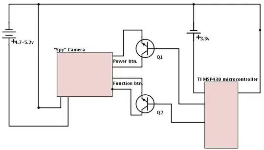
circuit diagram

When I test it on a breadboard with LEDs hooked up to the transistors instead of the camera, my program works fine. It "presses" the power button for 2.5 seconds to turn the camera, then sends brief pulses on the Function button to tell the camera to take a picture.

But when I connect the camera, the camera turns on, waits a few seconds, and turns it off. When I check the function button's transistor, it looks like it never even triggers.

My question is, should I be using transistors this way? Or did I screw something up?

Mar
  • 326
  • 3
  • 10
  • Can you provide more info on the switches? How are they wired? Are they connected to ground (pull down action) or to Vcc (pull up action). – alexan_e Jan 03 '14 at 21:27
  • I'm not sure whether they're pulled up or down. Is there a way I can check? I've got a multimeter. – Mar Jan 03 '14 at 22:16
  • Press each button and measure the joined contacts against ground, if you get a voltage then it's probably pulling the input high. If you don't get a voltage against ground it's probably pulling the input low, you can double check using the Ohm meter to see if there is a low resistance between the joined contacts and the ground. – alexan_e Jan 03 '14 at 22:29

2 Answers2

3

When you use transistors in this way, a series resistor must be included in the base line. 10k would be a good guess.

A transistor used this way sort-of works as a switch, but only in one direction. The emitter must be negative side (connected to the ground or - lead of the batetries). Your diagram does not show if this is the case, or whether you were even aware of this issue.

Wouter van Ooijen
  • 48,407
  • 1
  • 63
  • 136
  • The resistor to the base line is to limit current while still letting the signal through, yeah? As far as connecting the emitter ends to ground, I have the emitter and collector wired up arbitrarily to the two leads that used to have a push button. Is it possible I just hooked the one for the Function button backwards? – Mar Jan 03 '14 at 19:19
  • 25% one right, the other wrong; 25% vice versa; 25% both right; 25% both wrong. – Wouter van Ooijen Jan 03 '14 at 19:23
  • I'll take that as a "yes, it's possible". – Mar Jan 03 '14 at 19:24
  • @mouseas It's also _possible_ that neither of the button connections is connected to ground and your NPN transistors won't ever work. – Joe Hass Jan 03 '14 at 20:14
  • @JoeHass Ok. I'll try reversing the transistor and see if that works. If not, I'll have to come up with another solution. Would an optocoupler be likely to work if neither contact for the button is connected to ground? – Mar Jan 03 '14 at 20:26
  • Oh, you know what? I remembered I tried bypassing my microcontroller and directly connected the base of each transistor to +3.3v and they both seemed to work. But that was without any resistors in line. Hmm. – Mar Jan 03 '14 at 20:30
  • Any spare transistors around? – Wouter van Ooijen Jan 03 '14 at 22:00
  • I've got 20 or so, so yeah, I have spares. – Mar Jan 03 '14 at 22:17
0

If you don't know about the connections inside the camera I think it may be safer to use an optocoupler (mcu on the diode side, camera on the transistor side). Then you don't have to worry about grounds and you don't risk frying you camera.

You still need a current limiting resistor in series with the diode. Try 1k for a start.

The power draw would be a bit higher than with a transistor though , because the current gain is lower.

Nicolas D
  • 1,014
  • 1
  • 8
  • 11