16

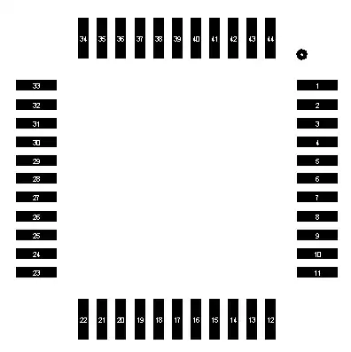
Sometimes when I order PCBs from a board house, I omit the bottom silkscreen for budgetary reasons. When I place surface-mount chips on the bottom of the board, I then end up with a footprint that doesn't indicate the chip orientation. This is annoying because it means that I need to verify the component placement and orientation during assembly, and this allows for errors when placing the parts.

How can I clearly indicate pin 1 with the remaining layers in a way that will be clear but not significantly impact the PCB size or cause issues when soldering? I'm assuming that I always have access to a solder mask layer and a copper layer.

W5VO
  • 18,303
  • 7
  • 63
  • 94
  • You might be doing onesy-twosy builds. But if you are doing any volume at all, then doing double-sided SMT is probably a bigger cost adder than a second silkscreen layer. – The Photon Jan 02 '14 at 17:32
  • @ThePhoton This is purely for one-off builds that will be hand assembled. I understand the cost trade-offs change when you start talking about automated manufacturing. – W5VO Jan 02 '14 at 17:40

4 Answers4

33

Have a differently shaped solder mask on pin 1.

For surface mount processors, you could have the pin 1 pad be noticably longer than the others.

Adam Head
  • 1,416
  • 2
  • 17
  • 27
  • 7
    I've also seen (and it's built in to the supplied libraries in Altium) pad 1 have rounded corners (in copper) while all the others are rectangular. – The Photon Jan 02 '14 at 17:29
17

I add a small dot in the copper layer near pin 1 but if the routing is too dense it may not be possible

enter image description here

alexan_e
  • 11,070
  • 1
  • 28
  • 62
  • 1
    alexan_e - Look at your profile - you may wish to save an image of your reputation before the year gets much older - [It looks like this](http://i.stack.imgur.com/2aYn3.jpg) :-) – Russell McMahon Jan 03 '14 at 11:07
  • 1
    @RussellMcMahon I haven't realized it, thank you for sharing. Now there is only stevenh standing in the way for a full house...maybe next year LOL :-) – alexan_e Jan 03 '14 at 11:28
4

Unless there are tight tolerances for the pad layout use a different shape pad for pin 1. i.e. oval instead of square.

Edit: the difference between this answer and previous answers is the difference between a solder pad and solder mask.

Jay
  • 81
  • 5
2

I agree with the previous suggestions for altering the pin 1 shape, whether that be in soldermask only, or the pin as a whole (Soldermask & Copper).

However, for aiding with the always inevitable debugging and troubleshooting later-on, pin shape & component pin 1 markings may be difficult to identify. It may be preferable to use a small "fiducial-like" marking on the board to emulate silkscreen. This will simply be a small copper marking (dot or line) with a soldermask opening over it.

Another idea may be to align all your components to have their Pin #1 in a specific orientation (usually handy for polarized 2-pin SMT devices, diodes, caps etc.)

SP4RT4N 44
  • 21
  • 2