A "moving coil" galvanometer shows a deflection proportional to current flowing through its coil due to very small voltages placed across its terminals.
Full scale deflection of a galvanometer typically requires between tens and hundreds of microamperes, corresponding to a voltage of tens of millivolts across the terminals. The coil resistance of a galvanometer is typically a few Ohms to a few hundred Ohms. Typical full-scale
For the sake of this explanation, let us assume a very sensitive galvanometer with 100 Ohm coil resistance, and 100 microAmperes current for full-scale deflection. Thus, by Ohms Law, the full-scale deflection will require 10 mV across the terminals.
To create an ammeter with a maximum current rating of 1 Ampere, this current must generate 10 mV across a "load resistor" or "shunt resistor". By permitting 1 Ampere to flow through a 10 milliOhm resistor, 10 mV is generated across this resistor. That's perfect for our purposes, so we connect the galvanometer across (in parallel with) this 10 milliOhm resistor:
simulate this circuit – Schematic created using CircuitLab
As the galvanometer's resistance (100 Ohms) is much much greater than the shunt resistance (10 mOhm), we can pretty much disregard the effect of paralleling the galvanometer's coil to our shunt. Thus, in effect the Ammeter we have created, has 10 milliOhms of resistance, which is pretty much negligible, and reads up to 1 Ampere current.
Now for a voltmeter. If we needed a full-scale reading of, say, 20 Volts, we would need to ensure that 20 Volts would cause 100 microamperes (assumption stated earlier) to flow through the galvanometer.
Ohms Law tells us that a resistor of 200 KOhms would pass 100 microAmperes through it, if exposed to 20 Volts. If we were to put our galvanometer in series with this current path, we'd have an excellent 20-Volt Voltmeter. In this case, again, the 100 Ohm coil resistance is negligible in comparison to the 200 KOhm resistor, so we can ignore it.
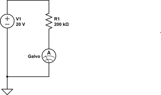
simulate this circuit
Note that in this case too, the galvanometer is illustrated as a current meter - because that is what it remains. The combination of the galvo, and the 200 K resistor in series with it, provides us a voltmeter that meets our requirements.
The above examples are extreme cases: Measurement of a small maximum current of say 1 milliAmperes instead of 1 A would require the current to pass through a resistance of 10 Ohms (to generate the 10 mV needed by the galvanometer coil). As this is a significant value comparable to the galvo's coil resistance, the actual shunt resistance value calculation would need to take the parallel 100 Ohms (coil) into account.
Similarly, for measuring small voltages by using our galvo as a voltmeter, the series resistor calculation would need to subtract the coil resistance value.
I am sure your textbook explains these calculations in greater detail.