8

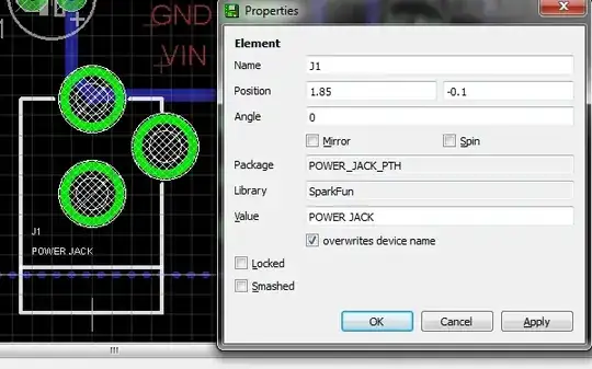
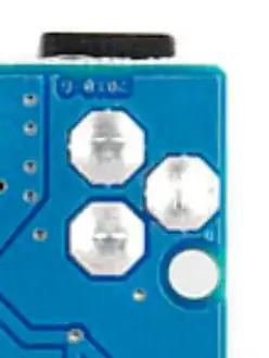
I am wondering how I can include a DC jack such as below in my PCB circuit:

DC jack

There are no such PCB packages in my library, so the first step, I presume, is to make a prototype with the exact dimensions as in the datasheet (correct me if I'm wrong).

What I am really confused about however is how to drill the holes in the PCB, given that I need a rectangular section instead of a circular one, for the three pins.

Nick Alexeev
  • 37,739
  • 17
  • 97
  • 230
triplebig
  • 1,407
  • 1
  • 19
  • 25

4 Answers4

8

You didn't mention which PCB layout program you are using, but if it is Eagle, the part is available in the SparkFun library. See images below.

Power jack - schematics Power jack - board

I drill the holes with the 3.2mm drill bit. I then place the connector on the PCB, touch both the connector terminal and the PCB pad with the soldering iron (hot) and push the solder in until it makes a little blob, nice and round. It takes quite a bit of solder, like in the image below. Watch out not to push the solder directly into the hole or it will go into the connector and destroy it.

Power jack - soldered

Bear in mind that I make my boards at home, so I have no idea how that is done with production quality, but mine gets firm and steady.

Ricardo
  • 6,134
  • 19
  • 52
  • 85
  • 2
    If you do find an apparently-suitable part in a library for a mechanical part like this, carefully check the footprint's dimensions against the physical part you have - different makers may place the pins in different positions. – Peter Bennett Dec 27 '13 at 22:32
  • @PeterBennett - Right! I usually layout the component on the board (using Eagle), print it in regular paper and then place the component over the paper to see if it fits. – Ricardo Dec 28 '13 at 01:01
4

To complement Ricardo's answer for Eagle, for Kicad this is available in Walter's excellent collection of libraries and footprints (including 3D models), dc_jack in the lib_w_connectors library and dc_socket in the mod_conn_misc library.

hlovdal
  • 999
  • 1
  • 13
  • 21
3

Yes, you will have to make your own footprint if you can't find one in the existing libraries.

I would make round holes for the pins - few board shops would have rectangular drills :-)

Peter Bennett
  • 57,014
  • 1
  • 48
  • 127
  • 1
    I would suggest oval holes. You'll get better soldering (and desoldering) if the hole is properly sized around the pin. – Adam Head Dec 27 '13 at 20:29
  • 1
    Round holes of the proper radius will work just fine. – AngryEE Dec 27 '13 at 20:55
  • 1
    You do not get better desoldering with snugly fitting holes; you get worse desoldering. If there is plenty of slack between a pin and plated hole, it is easy to vacuum out the solder from there, and separate the two. Where there is tight contact, you can break the bond thanks to the wiggle room you have. – Kaz Dec 27 '13 at 21:56
  • 2
    Oval holes or routed slots will proably add a mnaufacturing step, so may add to the board cost, and may not be available from the prototype board shops - best to keep things simple, and use round holes. – Peter Bennett Dec 27 '13 at 22:34
2

There is a suggestion (here) on how to go about specifying how you would like the through holes to be milled. They suggest creating a separate layer with the instructions/specifications.

Although as has been suggested it might be easier to just go with a round hole.

jmunsch
  • 131
  • 4