3

I'm very new in electronic stuff. I'm used to develop for desktop and mobile applications not for hardware products.

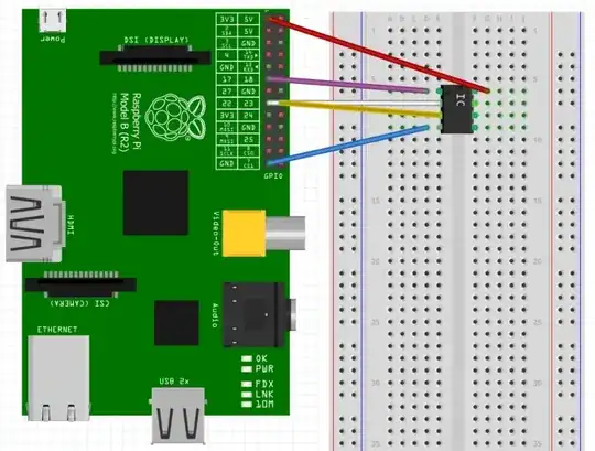
I try to wire up my Raspberry Pi board with an MCP4131 digital potentiometer. But it's not very easy to understand. I tried to build the projects from this previous thread. But Chris (the original posted in that thread) hasn't supplied a schematic of the wiring nor the successful running source code - so I tried my best to find out by myself: RPi with MCP4131 on a breadboard

What's the meaning if P0A, P0W, P0B? I tried to measure the voltage across P0A and P0B but it's always 0V. To which connectors should a LED, buzzer, ... be connected to regulate? (P0A-P0W or P0B-P0W)

My Python code look likes the following (tried to adapt the hint with writing out eight 0's before the value):

import time
import RPi.GPIO as GPIO

SPI_CS_PIN = 17
SPI_CLK_PIN = 23
SPI_SDISDO_PIN = 22 # mosi


GPIO.setmode(GPIO.BCM)
GPIO.setup(SPI_CS_PIN, GPIO.OUT)
GPIO.setup(SPI_CLK_PIN, GPIO.OUT)
GPIO.setup(SPI_SDISDO_PIN, GPIO.OUT)

def set_value(value):
    print "here"
    GPIO.output(SPI_CS_PIN, True)

    GPIO.output(SPI_CLK_PIN, False)
    GPIO.output(SPI_CS_PIN, False)

    b = '{0:016b}'.format(value)
    for x in range(0, 16):
        print 'x:' + str(x) + ' -> ' + str(b[x])
        GPIO.output(SPI_SDISDO_PIN, int(b[x]))

        GPIO.output(SPI_CLK_PIN, True)
        GPIO.output(SPI_CLK_PIN, False)

    GPIO.output(SPI_CS_PIN, True)

while True:
    for level in range(0, 128):
        print 'level:' + str(level)
        set_value(level)
        time.sleep(0.1)

    for level in range(127, -1, -1):
        print 'level:' + str(level)
        time.sleep(0.1)

Is there an easier way to use the MCP4131? I know the RPi supports the SPI protocol, but I'm not sure how to handle the multiplexing, because the RPi has one dedicated pin for SDI and SDO.

Nick Alexeev
  • 37,739
  • 17
  • 97
  • 230
dannyyy
  • 139
  • 1
  • 1
  • 2
  • 1
    where does PoA come from? Link? Hint? Also who the **** is Chris? Does he have a sister called Alice? – Andy aka Dec 23 '13 at 22:51
  • 1
    The MPC4131 datasheet indicates that POA and POB are the ends of the resistance element, and POW is the wiper (moving contact). You won't measure any voltage on these pins, but should be able to measure resistance. You should measure the advertised resistance of the pot between POA and POB, and a variable resistance between POW and either POA or POB, with the resistance depening on the porgrammed wiper position – Peter Bennett Dec 23 '13 at 23:23
  • Thank you Peter, I was too late in the night...After measuring the resistance instead of the voltage it's all fine ;) The code as well as the wiring seems to be working. – dannyyy Dec 24 '13 at 13:41

1 Answers1

2

Notice that your white cable is connected from SCK from your chip to RPi's pin 22. But in your code you have:

SPI_CLK_PIN = 23
SPI_SDISDO_PIN = 22 # mosi

So they are reversed. It should be:

SPI_CLK_PIN = 22
SPI_SDISDO_PIN = 23 # mosi

Also, note that the graphic is missing the connection of 3 pins of the digital pot:

  • Pin 5 goes to GND
  • Pin 7 goes to Vcc
  • Pin 6 will go to the anode of your LED (or whatever) and its cathode should go through a resistor to GND

For anyone searching for a solution to similar problems with MCP4131, here is the code that worked for me:

import sys
import time
import RPi.GPIO as GPIO

SPI_CS_PIN = 17
SPI_SDISDO_PIN = 22 # mosi
SPI_CLK_PIN = 23

def sleep(a = 0.1):
    time.sleep(a)

# Enables step by step checking by wiring some LEDs to those 3 terminals
def wait_a_key():
    print "waiting..."
    #raw_input()

GPIO.setmode(GPIO.BCM)
GPIO.setup(SPI_CS_PIN, GPIO.OUT)
GPIO.setup(SPI_CLK_PIN, GPIO.OUT)
GPIO.setup(SPI_SDISDO_PIN, GPIO.OUT)

GPIO.output(SPI_CLK_PIN, False)
GPIO.output(SPI_SDISDO_PIN, False)
GPIO.output(SPI_CS_PIN, False)

print "Setup"
GPIO.output(SPI_CS_PIN, True)
GPIO.output(SPI_CLK_PIN, False)
GPIO.output(SPI_CS_PIN, False)
wait_a_key()

def set_value(b):
    b = "0000" "00" "{0:010b}".format(b)

    GPIO.output(SPI_CS_PIN, False)
    for x in b:
        GPIO.output(SPI_SDISDO_PIN, int(x))
        GPIO.output(SPI_CLK_PIN, True)
        #For step by step checking: sleep()
        GPIO.output(SPI_CLK_PIN, False)
        #For step by step checking: sleep()

    wait_a_key()

    GPIO.output(SPI_CS_PIN, True)
    sleep()

try:
    for i in range(0, 100, 10):
        print 'set_value:' + str(i)
        set_value(i)
        sleep()
finally:
    GPIO.cleanup()
MondKin
  • 123
  • 6
  • Thanks for this, this worked for me. On a side note, after running this script, the pins have an invalid state for using the wiringPi library. You either have to reboot or run these commands: `gpio -g mode 7 out gpio -g mode 8 out gpio -g mode 9 alt0 gpio -g mode 10 alt0 gpio -g mode 11 alt0` – alana314 Feb 07 '17 at 08:41