4

enter image description here

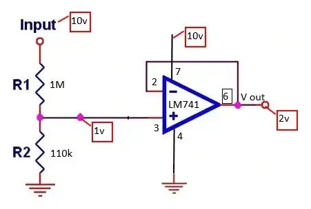
Have set up a voltage divider inputting 1 volt into a LM741 op amp to act as a voltage follower. For some reason I get 2 volts at the output. Have checked everything I can think of and can’t figure out why.

bigshop
  • 81
  • 1
  • 2
  • 4
  • 7
    WHY are people still using the LM741? It was old and out-specced by 10-cent op-amps in 1990! – Connor Wolf Dec 23 '13 at 02:56
  • [What's the uA741's appeal?](http://electronics.stackexchange.com/questions/8253/whats-the-ua741s-appeal) – RedGrittyBrick Dec 23 '13 at 13:24
  • Because as a beginner I saw it in just about every book and beginner type article so that's what I used. Now I know its not the correct type for me I have moved on – bigshop Feb 24 '14 at 18:52

1 Answers1

6

This is an easy problem to understand if you look at the datasheet.

LM741 electrical characteristics
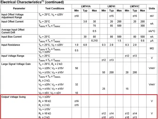
The LM741 needs headroom at each rail to operate. What this is saying is for +/- 15V supplies, the output could swing as little as +/- 12V. If you're running it single supply like that, I guarantee it's slamming the negative rail. Upgrade to a modern op amp. For this application, I would look for something CMOS with a rail to rail output. A couple examples: TLC2272, LMC6462.

Matt Young
  • 13,734
  • 5
  • 34
  • 61
  • Thanks for your reply. Im very much a beginner so could you expand on your answer some more. Can you suggest what better type of op-amp I might look at?. Im using this to reduce the voltages going into my daq card. – bigshop Dec 23 '13 at 02:16
  • Then take the op amp out entirely. Your DAQ card most likely has a high impedance input. – Matt Young Dec 23 '13 at 02:24
  • My daq card is only 144k input impedance and it loads the signal too much that's why I need to add the follower. – bigshop Dec 23 '13 at 02:30
  • And what are you using for R1 and R2? – Matt Young Dec 23 '13 at 02:31
  • R1 = 1meg, R2 = 11k – bigshop Dec 23 '13 at 02:33
  • 2
    You should really edit this question to reflect what you're actually trying to do. There is probably a better way to do this than attenuating a signal by a factor of 100. – Matt Young Dec 23 '13 at 02:39
  • Describe the signal. It is an AC that swings around 10V? How big are the swings? This circuit can be rescued: you can scale the signal to the appropriate lower level you want, **and** make it swing around some voltage higher than 1V so that the swings are within the input range of the op-amp. Does your signal need to be DC-coupled? – Kaz Dec 23 '13 at 03:06
  • 1
    Im measuring DC signals. Have changed my resistors now to attenuate 10:1. After reading Matt Young answers I now see why my circuit would not work. I now know I have the wrong type of op-amp for my application. By changing the power supply to the current op-amp to +10v and -10v I can now get the expected result. – bigshop Dec 23 '13 at 05:29