If an NPN BJT is being used as a switch, why is the load usually connected between +Vcc and collector? How is the performance affected if the load is connected between emitter and ground?
Asked
Active
Viewed 233 times
3 Answers
0
I think you will see the problem yourself if you remember that for an NPN transistor to pass large currents from the collector to the emitter you must cause current to flow into the base terminal. Because there is a PN junction between the base and the emitter, it is therefore necessary to raise the voltage of the base terminal about 0.6V above the voltage of the emitter terminal. Don't make the mistake of thinking that you just need to bring the base to a voltage about 0.6V above ground. That's a common misconception because you usually see the NPN transistor used with its emitter tied to ground.
You can also think of this from the emitter's point of view. If the voltage at the emitter starts to rise for some reason then the transistor will stop conducting current once the emitter voltage rises to about 0.6V below the base voltage. So, the emitter voltage can't ever be higher than the base voltage when the transistor is conducting. Now, think about the voltage you are using to turn the transistor on and off. The emitter voltage must always be lower than that voltage.
Joe Hass
- 8,447
- 1
- 29
- 41
0
The normal configuration is called common emitter. It is characterized by a modest amount of voltage amplification, and a modest amount of current amplification. This means that, with a low voltage and a low current, the transistor can switch a higher voltage and higher current.
The configuration with the load in the emitter is called common collector, or emitter-follower. It is characterized by a high current amplification, but no (slightly less than 1) voltage amplification. This means that, with a very low current, the transistor can switch a much larger current. But the input voltage must be at least the load voltage.
In a lot of cases the common-emitter is more appropriate, but in power end-stages you will often find the emitter follower.
There is a third configuration, the common-base, which is characterized by high voltage amplification and low (slightly less than 1) current amplification. It is not used very often.
Wouter van Ooijen
- 48,407
- 1
- 63
- 136
-
" ... It is not used very often." -> in a form where people recognise it for what it is. A long tailed pair, the basic functional block in almost all opamps, can be properly considered as am consisting of an emitter follower followed by a common base amplifier. But, I know you know that :-). – Russell McMahon Dec 21 '13 at 15:59
-
Hey Russel, you are using my own words against me! :) – Wouter van Ooijen Dec 21 '13 at 17:49
-
"Against"? Never, master! :-). ie I know you know that a common base/gate stage is the 2nd half of a long tailed pair and much used in integrated circuits. You were talking about its use in isolation where, indeed, it is not commonly used. A "nice" use is in RF input stages where a LTP allows a low noise design. You can do this with "valves". I had an old USAF ARC5 WW2 era recvr long ago, and fitted a dual triode in place of the existing front end RF amp tube. Misc components and the triode mounted in an existing valve base (possibly Octal?). It vastly improved RX performance. – Russell McMahon Dec 22 '13 at 09:49
0
If the load is connected between the emitter and ground then the configuration is what is known as common collector and in that configuration the emitter voltage is approximately 0.6v lower than the base voltage.
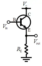
It is also called an emitter follower because the emitter voltage always "follows" the voltage of the base minus the base-emitter diode voltage drop (about 0.6v).
This mode is not convenient when you try to switch a load that uses a voltage higher than the voltage you connect to the base, so if you try to drive a 12v relay connected to the emitter with a microcontroller that feeds the base of the transistor with 3.3v or 5v then you will see that the relay actually gets 2.7v or 4.4v (for 3.3v and 5v input) which is much lower than needed.
On the other hand it can be very useful if you want to make a regulator, you can use a zener to drive the base with a constant voltage and the emitter output will keep a constant voltage approximately 0.6v lower than the base.
alexan_e
- 11,070
- 1
- 28
- 62