7

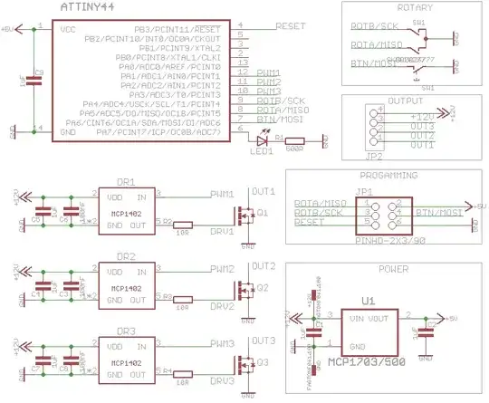
I have the following circuit:

enter image description here

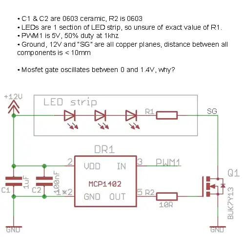
The MCP1402 MOSFET driver should be driving the BUK7Y13 N-channel MOSFET at 12V, but I'm seeing a much weaker signal which oscillates around 0.7V, preventing the gate from turning on the MOSFET.

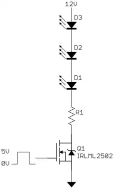
  • The load being driving is just 3 LEDs and a resistor in series, as described here. I've tried both a full strip, and a short section with just 3 LEDs.
  • I have tried adding an additional 4.7uF polarized capacitor between 12V and GND, to no effect.
  • I have three of these circuits and they all exhibit the same symptoms, so it's not faulty components.
  • Even with no load (no LEDs) the MCP1402 gets hot to the touch, but I don't think anywhere near it's max temperature.
  • I had previously tried the same circuit but with a FAN3229 driver and no R2, but got similar results.

The FET has a gate charge of 5nC and the driver can put out 500mA - this seems fine to me, but the circuit is not working and I'm at a loss. I presume there's something I haven't understood about the use of a MOSFET driver but I can't see what.

Edit:

Circuit Layout

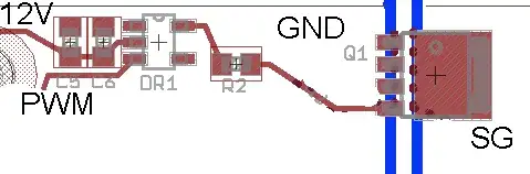
Here's an excerpt from the layout - there is a plane to the right of the right blue line which which is "SG" in both diagrams, connected to the low side of the LEDs. And the plane on the left of the left blue line is GND. The other two connects, PWM to control and the connection to the driver are clear.

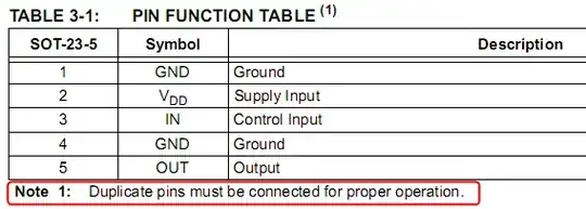
Pin 4 is the gate as you can see, pins 1-3 are the source to GND and the tab/base is the drain to SG.

"With no load" means with no LEDS being driven by the circuit, and yes I have confirmed with a scope a nice 5V square wave coming in from my MCU, so the signal is correct. I should also add I do see a very, very faint flicker on occasion from the LEDs, as I would expect with the gate switching partially on.

Edit 2:

Having ruled out the obvious, here's the full circuit and layout which I didn't post before for the sake of clarity.

Polygons SG1, SG2 and SG3 are red(top)/blue(bottom) to right of board, connected with many (thermal) vias. 12V polygon is blue(bottom) on lower half of board, GND is blue(bottom) on upper half and red(top) on most of the board. Power supply is large desktop supply and MCU is functioning as programmed at 5V, LED1 is working, PWM to drivers is working, it's just signal from the drivers. Components were all recently purchased from Farnell.

Full Cicruit enter image description here

Mike B
  • 111
  • 11

7 Answers7

7

What is wrong with your circuit is irrelevant from the point of view of getting a working unit.

There is no need for a MOSFET driver in this case. Use the IRLML2502 MOSFET and drive its gate directly from the digital output of the microcontroller. Check the IRLML2502 datasheet and you will see that it has a maximum guaranteed on resistance of only 45 mΩ with 4.5 V on the gate. You also don't need a resistor in series with the gate:

Yes, it really is that simple.

Olin Lathrop
  • 310,974
  • 36
  • 428
  • 915
  • Whoever downvoted this, it would be useful to explain what exactly you disagree with. I read this over again, and still think it is a good solution for the OP. – Olin Lathrop Dec 31 '13 at 13:11
  • Well, somebody might dislike the idea of driving mosfet without series resistor. Even if current is limited by weak uC pin. – BarsMonster Jan 03 '14 at 02:49
  • @Bars: If that is the reason, they should say so. In this particular case there is no need for the series resistor on the gate. There are cases where you need a series resistor, but too often people just add one religiously without thinking why. – Olin Lathrop Jan 03 '14 at 15:20
  • Olin, thanks - I'd come to the same conclusion myself actually and have already reordered the boards but with a PH3230S MOSFET - 5mΩ Rds(on) with Vgs=4.5V, same form factor as my existing choice. In hindsight I should have spend longer choosing a MOSFET, and abandoned my presumption that logic-level MOSFETs have bad Rds(on). Thanks and have my bonus with gratitude :-) – Mike B Jan 06 '14 at 11:48
  • @Mike: Thanks. Logic level MOSFETS can achieve low Rdson. Their limitation is usually low maximum D-S voltage. Note the IRLML2502 is only good for 20 V. That's no problem in your 12 V circuit. I'm just pointing out what the tradeoff usually is. – Olin Lathrop Jan 06 '14 at 12:14
6

My hunch is that you may have misinterpreted the pinout of the MOSFET. Instead of connecting the gate, you are driving source with a gate driver, while drain is connected to ground. The 0.7V, which you see is the forward drop across the body diode of the MOSFET.

In the fourth bullet in the O.P., you're saying "with no load [...]". Do you mean that: (a) the LEDs are disconnected or (b) the MOSFET gate is disconnected from the gate driver?

If you haven't done it already, you should do an experiment, where you disconnect the gate and observe the open circuit output of the gate driver.

Nick Alexeev
  • 37,739
  • 17
  • 97
  • 230
  • 1
    Thats my hunch too +1 – Andy aka Dec 20 '13 at 23:39
  • Thank you, good suggestions (also to Madmanguruman below). I've removed the MOSFET from the board and I still see the same avg 0.7V signal from the driver - specifically, at pin 5 on the driver or at either side of R2 in the layout above, and it looks like a clean square wave oscillating between about 0.5V and 1V (although my scope is a bit crap, so those are estimated). I get the same result when I solder a 1nF cap between gate and source. The signal is identical on all 3 circuits, although I only removed the MOSFET from one. – Mike B Dec 22 '13 at 23:13
  • Looking at your layout, I don't see glaring problems with pinouts. Well, I'll try to poke at a few more things. If you observe the supply voltage on the pin on the gate driver, do you see +12V ? – Nick Alexeev Dec 23 '13 at 00:11
  • Thanks Nick - yes, just double checked and input into drivers (pin 2) is 12V. – Mike B Dec 23 '13 at 11:37
5

Always split the problem into smaller pieces. You need to figure out if you have a driver issue or a MOSFET issue.

To debug the driver, remove the MOSFET from your circuit board and connect a small capacitor between the MOSFET gate and source connections. Your MOSFET has \$C_{iss}\$ of around 1nF, so use a cap close to that value. The driver should easily be able to swing that capacitor up and down.

If the driver isn't able to drive the capacitor properly, you have a driver issue (damaged part, layout misconnection, etc.) and you can focus your troubleshooting there.

If it can drive the capacitor properly, either your MOSFET is damaged or misconnected (as others here have speculated).

Adam Lawrence
  • 32,921
  • 3
  • 58
  • 110
5

Looking at your PCB, it's obvious that you don't understand the role of C5/C6, and what constraint that role puts to the way you may run their traces. It seems that you believe that the GND connection of those capacitors and the GND pin of the MOSFET driver can have a long-long trace between them. Well, that's not the case. They have to be as close as possible. Like, 1 or 2mm. Check the turquoise trace. enter image description here

The same is true for the other drivers as well.

Laszlo Valko
  • 1,988
  • 16
  • 15
  • Thank you, I suspect this was a part of the problem but was unable to verify it as my jury-rigged solder bridge shorted something. Never presume Eagle will do what you expect with polygons, particularly when it's creating thermals. – Mike B Jan 06 '14 at 11:52
2

The second ground connection is missing from your schematic, have you connected pin 4 to the ground?

Here is what the datasheet says

enter image description here

alexan_e
  • 11,070
  • 1
  • 28
  • 62
0

You mentioned above that you see a 0.7v Average signal from the driver with the FET removed? "it looks like a clean square wave oscillating between about 0.5V and 1V".

The Mosfet VGS(on) threshold is stated as 3V. The output pin of the driver should be approaching the rail voltage 0.25V (datasheet) so the Vo(h) of pin 5 should be about 11.75V. If you are indeed injecting a 1KHz 50% duty square wave then the average voltage should be read at about 5.5V. Does the oscilloscope indicate that the signal is acheiving VGS(on)?

I have come across the situation where an entire board run had damaged IC's. Li-Ion fuel gauges were fried to crisps during reflow and the damage could not be seen with the naked eye. None of them worked in the prototype batch and it left me scratching my head to no end. No design changes and the second run worked perfectly. Have you tried replacing the driver IC's? IOf they are not providing the 0-11.75V drive then they could be suspect as the layout and design appear to be good.

Martin
  • 866
  • 6
  • 7
0

Here is my suggestion :

  • Remove R2 and Q1 and replace DR1 with a fresh IC but lift pin 5 so it doesn't touch the trace on the board.
  • Probe the lifted pin and see if it has the appropriate signal swing (0 to 12V).
  • If it does, solder the pin down and check again. (if it doesn't there's something wrong with the driver IC).
  • After soldering pin 5 down, if the swing is still ok, then put in the R2 resistor. (if the swing is not ok at that point, then the trace from pin 5 to R2 has a resistive short to somewhere which you have to ohm out.)
  • After inserting R2, if the swing is ok, then there is probably something wrong with the MOSFET, although it seems you have already ruled that out. If the swing is not ok, then there is something shorted with the trace from R2 to the MOSFET and you'll have to ohm that out with adjacent traces.

The fact that it appears to go from 0.5V to 1.0V even with the MOSFET removed, implies that it may be shorted to a node with a voltage a little above 0.5V. It could also mean that something is being misinterpreted on the scope. My suggestion on that end is to do this debugging with the IN pin forced low and then with the pin forced high by either cutting the PWM3 trace or lifting pin 3 and soldering a wire to it.

Tom
  • 1