2

Is it possible to use Timer1 on an ATMega to generate a compare interrupt on OCR1A and PWM output on OCR1B? I've tried with similar to the following, but neither work with everything I've tried.

TCCR1A = _BV(COM1B1) | _BV(WGM11) | _BV(WGM10);
TCCR1B = PRESCALE1_8;
OCR1B = 0;


// set compare match register for 1000Hz 
OCR1A = 2000;
// turn on CTC mode
TCCR1B |= _BV(WGM12);

Side note: I know this is extremely similar to another question of my own, but that was regarding PWM on one timer and interrupts on another. This time I'm having trouble getting both out of the SAME timer.

Adam Haile
  • 1,603
  • 5
  • 31
  • 50

1 Answers1

3

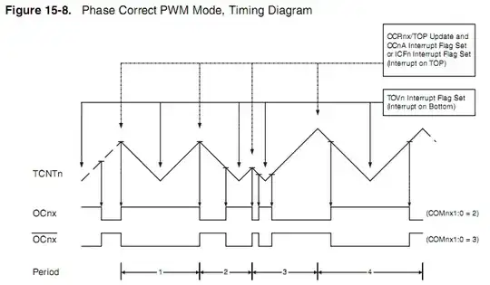
Your code sets the counter for phase correct PWM operation with top value 0x3FF so the first problem you'll face is that the compare match interrupts will not be triggered in equal intervals because of the way that this mode works which is count to the top and then change direction and count backwards.

The other problem is that the counter counts up to 1023 (0x3ff) and back to 0 so there is no way to ever get a match interrupt for a value of 2000 (OCR1A = 2000)

phase correct PWM operation:

enter image description here


This is a minimum code for mega328 running @16MHz that sets Timer 1 to generate a fast PWM with a frequency of about 1KHz (frequency set by ICR1 and duty set by OCR1B) and also gives a timer 1 overflow interrupt with a 1KHz rate

#include <avr/io.h>
#include <avr/interrupt.h>

// Timer1 overflow interrupt service routine
ISR(TIMER1_OVF_vect)
{
    PORTB ^= 1; // invert PORTB.0
}

int main(void)
{

    // Port B initialization
    // Function: Bit7=In Bit6=In Bit5=In Bit4=In Bit3=In Bit2=Out Bit1=In Bit0=Out
    DDRB = 0x05;

    // Timer/Counter 1 initialization
    // Clock source: System Clock
    // Clock value: 2000,000 kHz
    // Mode: Fast PWM top=ICR1
    // OC1A output: Disconnected
    // OC1B output: Non-Inverted PWM
    // Noise Canceler: Off
    // Input Capture on Falling Edge
    // Timer Period: 1,0245 ms
    // Output Pulse(s):
    // OC1B Period: 1,0245 ms Width: 0,12806 ms
    // Timer1 Overflow Interrupt: On
    // Input Capture Interrupt: Off
    // Compare A Match Interrupt: Off
    // Compare B Match Interrupt: Off
    TCCR1A = (0 << COM1A1) | (0 << COM1A0) | (1 << COM1B1) | (0 << COM1B0) | (1 << WGM11) | (0 << WGM10);
    TCCR1B = (0 << ICNC1) | (0 << ICES1) | (1 << WGM13) | (1 << WGM12) | (0 << CS12) | (1 << CS11) | (0 << CS10);
    TCNT1 = 0;
    ICR1 = 2048;
    OCR1A = 0;
    OCR1B = 256;

    // Timer/Counter 1 Interrupt(s) initialization
    TIMSK1 = (0 << ICIE1) | (0 << OCIE1B) | (0 << OCIE1A) | (1 << TOIE1);

    // Global enable interrupts
    sei();

    while(1)
    {
        // Place your code here

    }
}
alexan_e
  • 11,070
  • 1
  • 28
  • 62
  • Could I use Fast PWM instead? Not that I'm entirely sure how to do that :P – Adam Haile Dec 18 '13 at 22:56
  • @AdamHaile Depends what you want to do, if you want to get equal intervals for the compare match then yes, if it is just to set a higher top value (which will result in a lower PWM frequency) then you can use both modes with a custom top value set to the ICR1 register by selecting the appropriate PWM mode (using the WGM register values) – alexan_e Dec 18 '13 at 23:19
  • Yes... definitely want equal intervals. The Compare match is for doing multiplexing between different LEDs using the PWM signals. Any chance you could show some example code? – Adam Haile Dec 18 '13 at 23:28
  • @AdamHaile what is your specific MCU? And what about the PWM frequency? PWM can give a timer overflow interrupt once per period (TOV1 flag), maybe you can use that for your refresh – alexan_e Dec 18 '13 at 23:40
  • ATMega328P-PU. Have no idea what the PWM frequency is. Was using 8 prescaler, so 2MHz? I'm trying to get an interrupt at roughly 1000 Hz. – Adam Haile Dec 18 '13 at 23:49
  • @AdamHaile In phase correct or phase & frequency correct mode with top=0x3ff, the output PWM frequency=timer clock/(1023*2) so 2MHz/2046=917Hz , if you use the TOV1 flag (overflow flag) interrupt you can get interrupts at that rate – alexan_e Dec 19 '13 at 00:01
  • I'm confused by what you mean by top=0x3ff, what register is that? Any chance you could show an example? – Adam Haile Dec 19 '13 at 00:06
  • @AdamHaile That is not a register it is the top value of the PWM, the mode you have selected in your original code by `TCCR1A = _BV(WGM11) | _BV(WGM10);` is PWM, Phase Correct, **10-bit** , that 10 bit means **TOP value is 0x03FF** (it's in the datasheet) and is what actually sets the PWM frequency. – alexan_e Dec 19 '13 at 00:14
  • Ahh... but how exactly would one use the TOV1 ISR? – Adam Haile Dec 19 '13 at 00:19
  • Side note. I'm also doing PWM on Timer/Counter 2... am I going to have any issue with the PWM being at the same frequency/duty cycle? – Adam Haile Dec 19 '13 at 00:24
  • @AdamHaile Just enable the timer1 overflow interrupt `TIMSK1=(1< – alexan_e Dec 19 '13 at 00:26
  • Have the following now, but definitely not doing any PWM: TCCR1A = _BV(WGM11) | _BV(WGM10); TCCR1B = PRESCALE1_8; OCR1B = 0; TIMSK1=_BV(TOIE1); – Adam Haile Dec 19 '13 at 00:51
  • @AdamHaile , I have added a minimum working code in the reply – alexan_e Dec 19 '13 at 09:03
  • @AdamHaile Have you tested the code? – alexan_e Dec 21 '13 at 23:22
  • @alexan_e, For this code, are we assuming that some circuit (eg, transistor) is connected to OCR1B pin? – David Norman Aug 03 '14 at 20:51
  • @DavidNorman The code doesn't need any external component to generate the pulses at PORTB.0 and OC1B. The generated pulses can then drive any circuit the designer wants (withing AVR I/O specs). – alexan_e Aug 03 '14 at 21:01
  • @alexan_e, I am using a transceiver to module the signal. Do I have to hook up either TX or RX line on the transceiver to OC1B pin? Right now I have it connected to my RX0 and TX0 on the microcontroller (atmega328p). Is there a way to still be able to use signals from OC1B (internally not externally) to drive RX0 and TX0 pins. please note I am not using serial anymore so RX0 and TX0 are just GPIOs – David Norman Aug 03 '14 at 21:04
  • @DavidNorman Check figure 16.8 page 124 in the [m88 datasheet](http://www.atmel.com/images/doc2545.pdf). You can get an event at the top and bottom of the PWM using the output compare and timer overflow interrupts. I'm not sure what you are doing so I can't provide much help. Maybe you should post this as a new question. – alexan_e Aug 03 '14 at 21:23
  • @alexan_e, http://electronics.stackexchange.com/questions/123898/modulating-transceiver-using-atmega164pa – David Norman Aug 03 '14 at 22:26