7

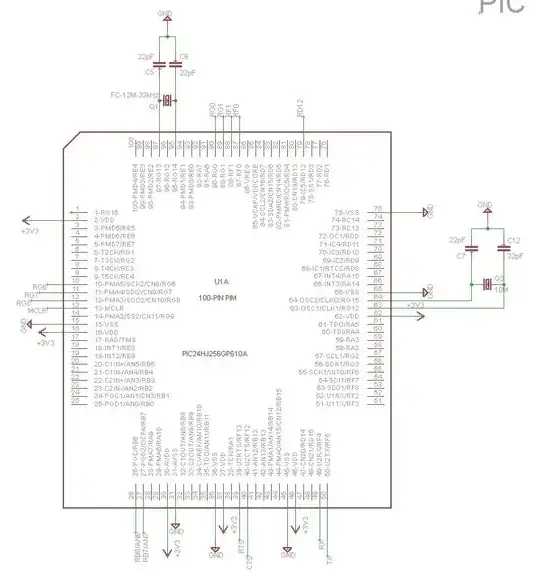
We designed a board with a Microchip PIC24HJ256GP610A on it. We've successfully used an ICD3 to program and debug the PIC on the Explorer 16 development board. We think we've followed the design guidelines found in Debugger's User's Guide:

enter image description here


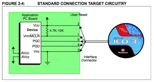
Edit: We use a 4.6k pullup resistor between MCLR and VDD.

Our PCEG/PGED interface are pins 26/27 on the PIC. These lines are exclusively connected to the chip and not used for anything else.


We power our board externally and the PIC is connected to this power supply circuit (3.3 Volts, enough power from this source).

Edit: We use some decoupling capacitors on our supply rails (C2, C8, C9 and C16, C18):

enter image description here enter image description here

However, when we try to connect and upload our program to the PIC, we get the following message in MPLAB X's output window:

Target detected
Target Device ID (0x0) does not match expected Device ID (0x77b0000).

This is an excerpt from our board's layout:

enter image description here

Can someone see the error or explain what could go wrong?

Norbert
  • 213
  • 1
  • 3
  • 8

4 Answers4

3

Edited per the updated information provided.

0x0 generally means no communication. Either a bad device, bad connections on the ICSP or power issues. I'll trust that your 3V3 rail 'works' for now.

Your _MCLR resistor and use of ICSP port 1 should pose no issue with the debugger.

Do you have sufficient decoupling, per the PIC24 datasheet? Decoupling capacitors must be installed as physically close to the PIC24 as the layout and pinouts permit:

enter image description here

You can see that for every \$V_{DD}\$ and \$V_{SS}\$ pair, you need a 100nF ceramic cap, and a 10 microfarad cap at \$V_{CAP}\$. What is shown in your schematics for the 3V3 rail doesn't appear to be sufficient, and more importantly, you don't have anything on \$V_{CAP}\$ (which is very bad.) Per page 20 of the datasheet:

A low-ESR (< 5 Ohms) capacitor is required on the VCAP pin, which is used to stabilize the voltage regulator output voltage. The VCAP pin must not be connected to VDD, and must have a capacitor between 4.7 μF and 10 μF, 16V connected to ground. The type can be ceramic or tantalum. Refer to Section 24.0 “Electrical Characteristics” for additional information.

Fix up your decoupling and let us know what happens.

Adam Lawrence
  • 32,921
  • 3
  • 58
  • 110
3

I agree with everything @Madmanguruman said. Here are some more things I would check.

1) How confident are you that the PIC24 is soldered down correctly? This includes all pins making connection, none shorted, right orientation, and so forth. Also verify that your programming header isn't inverted (6-1 instead of 1-6).

2) Can you probe PCEG/PGED with a scope to see if they toggle back and forth during programming? If so you can eliminate your programmer as a source of error. If they don't change, it could also still be a bad connection on your board pulling them down.

Matt
  • 1,276
  • 11
  • 18
1

Put a \$10\mu F\$ cap on the \$V_{reg}\$ pin (pin 85). The PIC24 core runs on 1.8V, and is internally regulated. That cap is required for the part to function. Read the datasheet.

Matt Young
  • 13,734
  • 5
  • 34
  • 61
0

I had the same error message type that proved to be software and not hardware as the error message implies. I had compiled code that gave no errors and loaded in the target correctly. When I changed the baud rate in a #define calculation for a bit-bang serial interface from 4800bps to 1200bprs without compiler error and attempted to load the code into the target through an ICD3, an error message was given: “Target Device ID (0x2060) does not match expected Device ID (0x2080).” The software design uses the unsigned 8-bit timer register TMR0 for timing the serial communications bit rate. Turns out by changing the baud rate, the calculation generated a value exceeding TMR0, resulting in the error message at load time. Once I adjusted the prescaler for TMR0, the calculations properly sized the value for the timer to accommodate the range of the 8-bit timer register and the Target Device ID error message discontinued.