2

A new problem I have is to create an automatic switch between two sources, only one of the sources should be active at a time. There is a "backup" source (5V battery), as well as another source. Once this source drops below a 3V threshold it should stop (and go back to the battery).

We wish to use a power (N- type)mosfets (with a \$V_{gs-th}\$ of 2V) to do the switching. The best circuitry that goes into the direction I've come up to is as following:

schematic

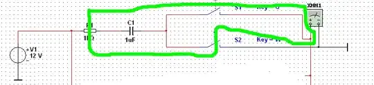
simulate this circuit – Schematic created using CircuitLab

(Notice the diode above the mosfet is to emulate a power mosfet)

Now the gate voltage is simply the \$\frac{2}{3} \cdot \left(V_{bat} - V_{var}\right)\$. (PS: I know this 2/3rd is not correct, it is currently included in the schematic so I have a point where I can edit the exact voltage difference)

Now this works for the battery: it is disabled as long as the variable source is above the threshold. However this isn't the case for when the variable source becomes too low. Then the variable source should be "disconnected" (so it can charge up again).

But I can't seem to add such a feature without breaking the current way.

paul23
  • 303
  • 2
  • 4
  • 11
  • I would consider using some IC to help with controlling the mosfets, like http://www.linear.com/product/LTC4353 (or similar) and then wiring up the enable inputs to do the prioritizing if a simple "power-OR" is not sufficient – Bjorn Wesen Dec 17 '13 at 02:00
  • Some how i didn't get your schematic properly. How the voltage of Vgate is 2/3(vbat-vvar), both sources doesn't have same reference to just substract it directly nor they are in series... 1N4148 has reverse breakdown at min 20v specified, if current has to go through MOSFET, it has to flow from Drain to Source and D2 should be reverse biassed.... – user19579 Dec 17 '13 at 09:23
  • @user19579 The two sources have the same reference, their positive pole is connected and R1, R2 form a voltage divider between the two source negative pole – alexan_e Dec 17 '13 at 22:42
  • Yes, i agree with you regarding reference, voltages of the sources will be added/subtracted when they are in series, regarding 2nd question, D2 reverse bias voltage is around 20V, how can current will flow through MOSFET without passing through D2(Reverse voltage of 20V can't be geenrated in this circuit) – user19579 Dec 21 '13 at 06:34
  • What about having a large capacitor to discharge current during the switch? The capacitor could keep the current running, I think. (disclaimer: only once tried this, and with very low voltages.) – Wyatt Ward May 04 '14 at 19:11

1 Answers1

0

Well I finished it, basically I had to switch the source instead of the drain using comparators to prevent the transistors of acting like resistors and draining power. For those interested here falstad simulation the actual circuitry what we choose/created is placed.

It basically switches either one of them (by means of a comparator, op amp in circuit, - I simply forgot active items when placing this question). It switches based on some reference values. Experience in practical comparators dictated now that the source for the comparator always should have a higher voltage than both inputs - thus the inputs should simply be halved. Also from experience we had to add a "pull up" resistor. But other than that the circuit worked.

The digital schematics are there to provide hysteresis as the solar cell array can only provide power for half the time (values of current source & capacitor bank are adapted to be able to simulate without waiting hours).

paul23
  • 303
  • 2
  • 4
  • 11