4

I'd like to build a tiny RC car that can run indefinitely without the need to charge. Bumper cars have strips of power on the ground and according to Wikipedia this is how they work:
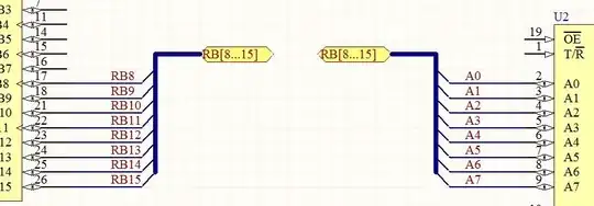
ground grid

"Uses alternating strips of metal across the floor separated by insulating spacers. The alternating strips carry the supply current, and the cars are large enough so that the vehicle body can always cover at least two strips at any one time. An array of brushes under each car make random contact with whatever strip is below, and the voltage polarity on each contact is sorted out to always provide a correct and complete circuit to operate the vehicle."

Has anyone attempted this before on a smaller scale? I'm not quite sure the circuit required to achieve this on a 5V~ scale, and the type of "brushes" that would be required. Any links or direction would be greatly appreciated thank you!

Edit: Alternatively I'd love if anyone had any ideas on how to keep a power cable directly above a car as it moves around a closed space (so if there were multiple cars they couldn't tangle on each other's wires).
Titan
  • 189
  • 1
  • 6
  • 4
    I believe the trick is using 3 sliding contacts and a full bridge three phase rectifier circuit. The three contacts must not be placed on the same line and have a certain distance between them so they're are always connected two power strips. – jippie Dec 16 '13 at 19:03
  • Sounds like a train set with an added dimension!! – Andy aka Dec 16 '13 at 19:47
  • 3
    The old-fashioned bumper cars had a pole that went up and made contact to a metal ceiling, and then the floor was another terminal. – W5VO Dec 16 '13 at 20:40
  • @W5VO that's correct, I'm trying to re-create the modern ones that have no pole. – Titan Dec 16 '13 at 20:40
  • Also consider inductive power transfer or "IPT". – Russell McMahon Dec 17 '13 at 11:33
  • @RussellMcMahon what about covering the floor with http://www.seeedstudio.com/depot/wireless-charging-module-p-1354.html?cPath=155 – Titan Dec 17 '13 at 15:42
  • @GreenGiant See studio unit could have a single physically larger coil as TX and smaller coil (perhaps existing) as RX using existing electronics. BUT search as I suggested and you will find many descriptions of similar. Starting with the seed studo unit is a good way to get going. Making a larger coil with the same inductance (fewer turns) would be "not too hard" [tm]. – Russell McMahon Dec 17 '13 at 21:46
  • My immediate idea for the brushes would be to imitate the system used on Scalextric cars - soft braided wire brushes. You would have to keep them short enough to avoid shorting between the positive and negative strips, though. – Simon B Sep 28 '16 at 16:08
  • The alternate brush type would be to use common commutator/slip-ring brushes from DC motors. – KalleMP Sep 12 '17 at 21:37

3 Answers3

6

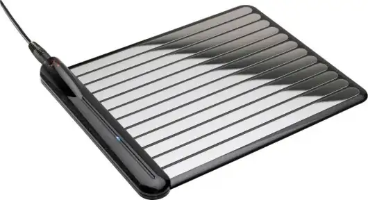
What you're describing is already a available product for charging mobile phones:

enter image description here enter image description here


Basically, the metalic strips are alternatively power or ground.

The arrangement of contacts on the mobile device is somewhat arbitrary, but the idea is to ensure that no matter what the physical orientation, there will always be at least one pin contacting one of the V+ strips, and one contacting a ground strip.

Then, you just feed all the contacts into a multi-phase rectifier (like the schematic in Nick Alexeev'a answer), and you get power out.

Connor Wolf
  • 31,938
  • 6
  • 77
  • 137
  • 3
    I think that is neat and I wouldn't mind a phone that charged like that, but I don't think a couple of pictures absent a schematic, some discussion, or any suggestion of how it works provides OP any help at all. – mikeY Dec 17 '13 at 06:17
5

Don't know if anyone had attempted this. But, obviously, this should be possible.

This is just an illustration of the rectifier idea, which @jippie wrote in his comment. +1 to him, by the way.

enter image description here

At least one contact (brush) should be on a positive strip, and at least one puck up contact should be on a negative strip. This circuit will "sort out" the polarity. More contacts with diodes can be added, if necessary.

The insulating gaps between the strips should be wider than the pick up contacts (brushes). This would prevent a short circuit from positive strip to negative strip directly through a single brush itself.

I would consider a supply voltage higher than +5V, which is mentioned in the O.P. Perhaps +24V. But, this will be dictated by the choice of motors.

Nick Alexeev
  • 37,739
  • 17
  • 97
  • 230
  • Excuse my ignorance, but is there any reason you chose 4 brushes, is that how many you would recommend per car (I'm assuming the brushes are on the bottom of the car)? Would you recommend any particular brush for this example? In your circuit all the strips look to be the same polarity how do you differentiate which is negative? Sorry I have very basic electronics knowledge currently :( – Titan Dec 16 '13 at 20:51
  • 3
    I guess you indeed need a fourth brush in case two brushes end up on the insulation in between strips. With three you would have a problem, with four it should be solvable. – jippie Dec 17 '13 at 07:14
  • If I'm only powering 5V circuits (raspberry pi) would +5V still OK? What would you recommend for those diodes (I presume they are all the same)? – Titan Dec 17 '13 at 08:30
  • Also since this would be their only power source I'm guessing I should use an Uninterruptible Power Supply e.g: https://www.modmypi.com/pi-modules-upis-basic?filter_name=power%20supply&page=2 for those moments when the brushes aren't making contact so the Pi doesn't turn off! – Titan Dec 17 '13 at 11:25
  • @GreenGiant You are going to lose about 0.5V in the diodes (assuming you use schottkys, 1.2V for normal silicon). If you need 5V on the car that implies 5.5V on the ground. If you place the contacts correctly you can in theory be sure that you will always have power. In reality you'll probably get lots of brief dropouts. At the very least a large capacitor on the supply to the Pi is a good idea. And keep the Pi supply isolated from the motor supply, that way your power reserve doesn't have to cope with the motor power draw. That'll probably involve another diode drop. – Andrew Sep 28 '16 at 15:51
2

Although you can get away with 4 contacts arranged with a central on surrounded by 3 more at 360/3 degrees with a spacing of 2/3 of the distance between conductive strip centres. You really want 6 contacts, arranged with 1 in the centre and the other 5 arranged at 360/5 degrees intervals around the central contact with a spacing of 2/3 of the distance between conducting strip centres. The with of the pickup contacts should be no more that 2/3 of the width of the insulating strips. This ensures that you will always have at least 2 contacts connected with at least 1 contact on positive and 1 on negative polarity strips. I would use a polarity resolver comprised of 12 Shottky Barrier Rectifier Diodes (typical Vf of 150mV @ 10Ampere. Also use a 47000uF reservoir capacitor and a few 100nf for transient suppression.

Dave
  • 21
  • 1