6

Motors in general have always been a difficult subject that I cannot fully wrap my head around. Considering DC motors, what determines the rate at which the motor spins?

It was my understanding that a permanent magnet created the field by which the current through the motor would act against via the conductor's induced field. As current increases then the induced field would thus increase - thereby increasing the rotational speed.

enter image description here

However, I have read quite a bit of material that has led me to realized that I was incorrect. Namely, what is said at this link about DC motors: DC Motors

For example, the same circuit schematic as above produces (considering back emf) the governing equations:

enter image description here

So we have the current through the motor as a function of the back emf.

Is the back emf a function of the load on the motor? Is it that the emf is generated in such a manner that current is limited by the lessening of the potential difference between it and the supplied voltage?

The governing equations dictate that if the applied voltage is lowered then the back emf decreases further which in turn will decrease the current demanded by the circuit (through the motor).

So, is the current through the motor just an indirect indication of the speed, or how does the current otherwise affect the operation?

Are all DC motors (aside from brushless) similar?

sherrellbc
  • 3,431
  • 6
  • 35
  • 62
  • 1
    "The emf is generated in such a manner that current is limited by the lessening of the potential difference between it and the supplied voltage?" CORRECT . "Is the current through the motor just an indirect indication of the speed?" CURRENT INDUCES TORQUE . If induced torque exceeds demand (load), speed can increase. As speed increases drag increases, counter EMF increases, and speed stabilizes. – Optionparty Dec 14 '13 at 20:29

3 Answers3

5

At the end of the day you have to realise an Electrical Machine is basically an electrical energy to mechanical energy converter that utilises magnetic fields as the link. The magnetic field/flux is either generated by magnetics or via electromagnets.

Motors in general have always been a difficult subject that I cannot fully wrap my head around. Considering DC motors, what determines the rate at which the motor spins?

The rate the electrical machines rotor will spin is fundamentally the same for all electrical machine types (Induction, sync, SR, BLDC, BLAC, brushed, hysteresis ...).

The rate of change of flux.

How this rate of change is created is very specific to each machine. But basically by creating a magnetic flux on the stator & the rotor, the rotor will attempt to align itself just like magnets do. This Electro-magnetic torque manifests itself as mechanical torque (due to being perpendicular to a freely rotating axis)

A torque acting on some inertia results in an acceleration that would want to take the rotor to infinite speed.

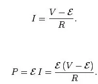
It can't because of Lenz's law. You now have a rotating magnetic field passing by coils, this induces a voltage which opposes the voltage source you are using to force current into the electrical machine to generate a magnetic field to produce EM_Torque.

The faster you go, the higher this voltage, the more it opposes the voltage source you are using. At some point you are no longer able to force current into the windings to create a magnetic field => no more EM_Torque --> no more rotor torque --> no more acceleration.

You have now reached your maximum unloaded speed.

As mentioned different machined create the changing flux by different mechanism

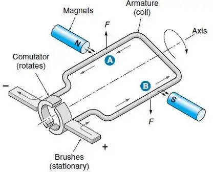
  • Brushed Machine (DC stator DC rotor)

PM stator & a wound rotor, brushes are used to transfer electrical power to the rotor to create a DC current and thus a unidirectional magnetic field on the rotor. Apply the voltage source and the rotor will turn to align itself. This causes “commutation” to occur via the brushes and the rotor magnetic field is changed pushing it away from the present stator pole & attracting it to the next.

More voltage ==> more EM_Torque ==> Faster commutation

  • Syncrounous Machine (AC stator DC rotor)

Wound rotor, Wound stator. Power is usually transfered to the stator via a Main-Exciter (basically a rotating transformer) and it produced a DC current in the rotor that does not change direction. The Stator is then excited with an AC voltage source. The rotor will “lock onto” this varying stator field and will be essentially dragged around with it. To increase the speed of a Synchronous machine the frequency of the voltage source to the stator is changed: Higher == Faster.

  • BLAC, BLDC (AC stator, DC rotor)

These are basically just Synchronous machines but they have permanent magnets on the rotor. Higher the stator frequency the higher the rotor speed. AC & DC just comes from the type of current control that is used.

  • Switched Reluctance (AC stator ... rotor)

Beautiful machines, salient rotor NO WINDINGS, NO FIELD GENERATION. Wound stator. The stator is excited to produce a flux. An unaligned rotor will experience reluctance torque and attempt to align itself to minimise the reluctance in the present magnetic cct ==> mechanical torque ==> acceleration. Once alignment occurs you stop firing the stator and let the rotor “coast” for a short period before firing again

  • Induction machine. (AC stator, AC rotor)

Wound stator, wound rotor. Unlike a synchronous machine however, the rotor windings are usually shorted (creating a squirrel cage like construction). Applying an AC voltage to the stator creates an AC magnetic field. This induces a voltage on the rotor & because it is shorted produces a current which in turn creates a magnetic field to be dragged around by the rotating stator field

  • Such a wonderfully throughout answer. So, as you say, the back emf is governed by Lenz's Law due to the permanent rotor magnet passing by the coils. So, is the back emf proportional to the rotors speed, or inversely related? – sherrellbc Dec 14 '13 at 21:33
  • Generally yes. There are two "constants" associated with electrical machines: Kt (torque constant) and Ke (BackEMF constant). How "constant" they are or whether they depend on other machine specific characteristics is machine topology dependant. In its simplest form V = Ke*w and T = Kt*i –  Dec 14 '13 at 21:46
2

I sometimes think of an ideal motor. Ideal in that it has no resistance, no friction. It acts like a generator with an output voltage of Kf, where K is a constant that depends on the motor design, and f is the frequency. This is not too bad for a permanent magnet motor. You apply a voltage and it draws current and spins up. It reaches a constant speed and no longer consumes power, so the current is now 0. The speed will be given by V = Kf so the generated voltage just opposes the applied voltage so that is why the current is 0.

You can also use this to think about small deviations from the ideal and what they would do.

Not very rigorous, but gives me some insight.

russ_hensel
  • 2,904
  • 16
  • 12
0

You seem to be missing that a motor is also a mechanical machine. Newton's second law is very relevant, saying that force \$F\$ is the product of mass \$m\$ and acceleration \$a\$:

$$ F = ma $$

Here, the force is the torque produced by the motor. If this torque is equal to the torque offered by the load (by friction, for example) then there will be no net force, thus no acceleration, and the motor will spin at a constant speed, whatever that happens to be. If the motor's torque is more or less, the mechanical load accelerates or decelerates.

The torque of the motor, as a first approximation, is proportional to the current through the motor. More current results in a stronger magnetic field, thus more torque. The motor may spin faster, if there is net torque in that direction, according to Newton's law above.

As the motor spins, the rotor also moves through the stator field. It is, essentially, a generator at the same time as it is being a motor. The back-EMF is, as a first approximation, proportional to motor speed. The back-EMF appears in series with the inductance and resistance of the motor windings, and in the most intuitive situation where the mechanical load isn't forcing the motor to run backwards relative to the voltage applied to the motor terminals, the back-EMF opposes the applied voltage (Lenz's law).

So, if you hook a motor to a 12V battery, and it's turning fast enough that the back-EMF is 10V, then it's like you are applying 2V to the motor. This explains the equation:

$$ I = \frac{V-\mathcal{E}}{R} $$

\$ V-\mathcal{E} \$ is really just the net voltage applied to the motor, so this is just Ohm's law: \$I=V/R\$. We can do this because real motors have significant DC winding resistance.

Here's a neat mental exercise: what would happen if you had a motor with zero winding resistance, and an ideal voltage source to power it?

$$ \lim_{R \searrow 0} \frac{V-\mathcal{E}}{R} = \infty $$

That is, as the winding resistance approaches 0, the current drawn by the motor approaches infinity. Since force is proportional to current, force also approaches infinity. Thus, a motor with no resistance has perfect speed regulation: any attempt to deviate from the speed set by the applied voltage results in an infinite current which results in infinite force to correct the speed discrepancy. The current through the voltage source will be proportional to the force required to maintain that speed.

Real motors, having some resistance, only approximate this behavior. If connected to a voltage source (car battery) then if you try to slow the motor (brake it with your hand) the back-EMF decreases, which results in more net voltage across the windings, which increases current, which increases force, which makes the motor try to not be slowed by your hand. The extent to which the motor is good at doing this is inversely proportional to the voltage source and motor's series resistance.

Phil Frost
  • 56,804
  • 17
  • 141
  • 262
  • What is meant by `stator field`? Are you referring to the rotor moving through the permanent magnetic field? Also, when back EMF is generated, the polarity is such that it opposed the polarity of the supplied voltage, V. When I have read of back-EMF protection, I noted that diodes are ubiquitously used and are placed in such a way to be reverse biased by the induced EMF voltage. How is it that when the main supply, V, is shut off that this reversed biased diode does anything to mitigate the damage to the motor? – sherrellbc Dec 14 '13 at 23:27
  • `If this torque is equal to the torque offered by the load (by friction, for example) then there will be no net force, thus no acceleration, and the motor will spin at a constant speed` If there is no net force then shouldn't it be that there is no rotation at all? The applied torque equals the opposing frictional forces and the motor is stalled. What am I missing here? – sherrellbc Dec 14 '13 at 23:28
  • The thought experiment regarding the limit of the winding resistance is an interesting one. That is to say that motors will draw more current in frigid environments providing identical mechanical work. Furthermore, this conclusion excites the mind even more considering that most electronic equipment tends to work efficiently in colder environments. – sherrellbc Dec 14 '13 at 23:30
  • @sherrellbc The stator field is the other magnetic field that works against the rotor field. It could be permanent magnets, or it could be another winding, depending on the motor design. Regarding motion and net force, I think you should review Newton's laws of motion. Also, ambient temperature won't affect winding resistance very much, and that it draws more current doesn't mean it's "less efficient" or "worse". In fact, the resistance represents electrical energy lost to heat, so as resistance goes down, the motor becomes *more* efficient. – Phil Frost Dec 15 '13 at 09:38