I'm wanting to count how often a water pump turns on, how long it's on for and when it turns off for an extended period of time. My plan was just to monitor the pressure switch, which is at 120v on 1 leg and write the data into a MSSQL database. What's the best way to get this data safely?
Asked
Active
Viewed 1.3k times
7
-
1Related: http://electronics.stackexchange.com/q/7728/2118 – tyblu Jan 23 '11 at 23:50
8 Answers
8
My plan was just to monitor the pressure switch, which is at 120v on 1 leg
The most common methods would be to use current (I) sensor to detect current flow when the pressure switch is activated (engaged). Such as Hall effect IC sensor, current transformer, or high voltage input Opto-isolator.
What's the best way to get this data safely?
Using a current detection method that also provides circuit isolation from the AC mains to your digital interface. Basic isolation methods include galvanic isolated (no current flow between isolated sides), opto-isolation (optical), and capacitor-coupled isolators.
I believe the most basic, yet low cost and non-invasive method of monitoring would be to use a split-core current transformer such as SCT-013-000 (US) (or UK). As you only are interested in on/off you can use a voltage divide circuit to meet digital logic level thresholds or make use of an ADC if available on the microcontroller assuming you are using one.
The load resistor (R_burden in the voltage divide circuit) value is based upon the current range, which depends on your motor. If the motor is 1 HP (horsepower) 110-120V motor, let's assume it is rated at 750 Watts (replace with actual specs from motor), so the current range is less than 8 Amps, let's round that to 10 Amp. Using the previously suggested current transformer sensor, with a turn ratio of 1:1500, that would be:
10 Amp (rms) * sqrt(2) = 14.142... Amps (peak-peak)
14.142 A / 1500 turn ratio = 0.0094 A = 9.4mA (secondary coil)
2.5 V / 0.00942.. A = ~ 265 Ohm R_burden so as to provide a mid-point (2.5 V) output at 5 Amp, or full-range (5 V) at 10 Amp for 5 V dc logic level.
Since the power (P = I*V) is 0.01 Watt, a 1/4 Watt resistor would be fine.
From there you should be able to interface a low-level (voltage & current) signal to whatever device you wish to use to send such data to the computer with the (logging) database. Typically a microcontroller with an ADC (analog to digital converter) and a serial, Ethernet, or USB interface would be the "glue" device between the sensor's circuit and the database computer. (IMHO MS-SQL is overkill (and expensive), SQLite would be fine)
If you are not familiar with microcontrollers, I would suggest using one with a friendly high-level easy to user interface, and hobbyist-oriented presentation such as the Arduino or PIC-AXE. They are more expensive than a stand alone or "naked" microcontroller per device or board, but the development environment is more newbie friendlier and for an one-off the one unit cost may be offset by the not having to purchase a SDK, reference documentation, or 3rd-party tools (high level language compilers) for a more traditional device such as the Atmel AVR or Microchip PIC microcontrollers.
3
mctylr briefly mentions a Hall effect sensor, and that's a good solution. Allegro is a well-known supplier of Hall sensors, like the ACS712.
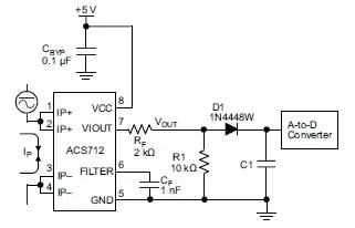
"Rectified Output. 3.3 V scaling and rectification application for A-to-D converters. Replaces current transformer solutions with simpler ACS circuit. C1 is a function of the load resistance and filtering desired. R1 can be omitted if the full range is desired." (from the datasheet)
[Added - Note: In this context - as an on/off sensor - the above circuit is fine - but it is incredibly non-linear if magnitude signal measurement is desired, as the diode drop is outside the ACS712' control loop. The ACS712 is ~=$3 in small quantity - adding even a cheap opamp will greatly enhance cct performance. Allegro should be ashamed. See above data sheet application 2 page 12 for a vastly superior circuit. Take output after D1 - FET circuitry not needed - RMc.]
Adam mentions the optocoupler solution.
In this and this answer I extensively describe how to use this.
-
@Stevenh Just came across this answer 2.5 years on. The 1st circuit is terrible in many cases if measument of signal level is wanted. It comes straight off application 4, page 12 of the data sheet that you cite, so Allegro are at fault. As a quick and ready solution it has its place but the diode plays havoc with the linearity of the signal. Using the application 2 cct immediately above it up to the cathode of D1 is VASTLY superior. It needs an opamp but gives a "precision rectifier" and very very much better results.. – Russell McMahon Dec 15 '14 at 06:39
3
These pages contain very interesting information on how to sense voltage and current in a non-invasive way. Have a look at it :)
Klaus
- 163
- 6
-
1Those pages do have good information right now (two months after you posted), but it will be better if you can summarize/quote (use the `"` button) the relevant parts of those pages. If that link goes dead, your answer is pretty useless as is... – Kevin Vermeer Mar 19 '11 at 05:01
3
I'd put a current transformer in the supply to the pump, and monitor the rectified output with a suitable MCU, sending the data with a time stamp to the data base.
Leon Heller
- 38,774
- 2
- 60
- 96
2
I'd connect this switch through optocoupler to DCD pin on PC serial port or one of the data pins on the parallel port
jet
- 217
- 1
- 5
-
Interesting. Then you just write an app that listens on that port? Would I need a resistor in serial of the 120v side? – asp316 Jan 24 '11 at 00:18
1
With a LM324 using two of its four Op Amps in comparator mode like in this schematic:
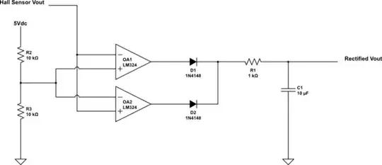
simulate this circuit – Schematic created using CircuitLab
Chris
- 11
- 1
1
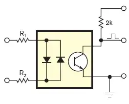
When I've done this in the past I've used an AC optoisolater, such as this Vishay SFH620A from Digikey, and a suitable resistor. Put the resistor in series with the optoisolator input, then connect to the AC line. The output will be active when there is AC power on the line, and will be inactive when there's no power.
There will be inactivity during each zero crossing, so you might want to use a capacitor on the output to provide a smooth output signal which will drop shortly after the power goes off.
Then you can connect the output to anything that you can use to log the usage.
Adam Davis
- 20,339
- 7
- 59
- 95
1
I know I'm late but for those that follow, the Fairchild HCPL-3700 will directly take AC or DC from 5 to 240 volts and produce a logic output.
Renan
- 5,090
- 2
- 27
- 45
Derric Tubbs
- 11
- 1