9

enter image description here

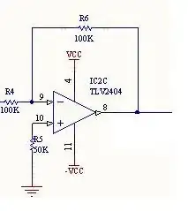
Here in the Figure R5=50K. This resistor value is not in the equations to obtain output voltage, and in many tutorials non-inverting input is directly grounded without a resistor. What might be the reason to use it here?

Fizz
  • 14,355
  • 2
  • 43
  • 97
user16307
  • 11,802
  • 51
  • 173
  • 312
  • The same question but for a non-inverting amp at http://electronics.stackexchange.com/questions/145897/use-of-100k-ohm-resistor-along-with-0-1uf-capacitor – Fizz Jan 13 '15 at 22:18

2 Answers2

10

R5 equals R4 || R6 (resistors in parallel) calculated as $$R_5 = \frac{R_4 \cdot R_6}{R_4 + R_6}$$ and its purpose is to balance the two inputs of the opamp, it cancels the differences caused by the opamp input bias current

http://www.ecircuitcenter.com/Circuits/op_ibias/op_ibias.htm

Phil Frost
  • 56,804
  • 17
  • 141
  • 262
alexan_e
  • 11,070
  • 1
  • 28
  • 62
  • the amplifier in the circuit is: ti.com/product/tlv2404. Can I just use a 751 instead? The inout signal is DC coming from a potentiometer varying between 0V and 15V – user16307 Dec 12 '13 at 15:11
  • You mean LMV751 ? – alexan_e Dec 12 '13 at 15:29
  • yes or the equivalent one. i mean i dont really understand why they use tlv2404 for this. – user16307 Dec 12 '13 at 15:49
  • LMV751 absolute max supply voltage is 5.5v, you can't use it for 15v – alexan_e Dec 12 '13 at 17:45
  • do you think any op-amp with 15V supply voltage could be used instead in this application? – user16307 Dec 13 '13 at 11:56
  • If the opamp is specified for 15v supply and it is stable with a gain of 1 then I don't see why it wouldn't work. If your input voltage can reach the same level as the supply then you should select a rail to rail opamp of use a higher supply for the opamp. – alexan_e Dec 13 '13 at 12:06
6

DC balance, aka input offset compensation.

Some opamps take a significant input current on each input pin - let's say 1 microamp. Work out the input impedance on the -ve input : 2 * 100k in parallel, giving 50K input impedance. Now that microamp input drops 50mv across that resistor, giving an output voltage of 50mv * the gain.

R5 compensates for this by dropping a matching 50mv on the other input, restoring the DC output to its correct value.

In practice there is also a voltage difference and a slight current imbalance between the inputs; called "input offset voltage" and "input offset current" which vary between amplifiers. This leaves an imbalance of (50k * offset current) + offset voltage at the input.

Some opamps draw tiny input currents; using these you can omit R5.

  • the amplifier in the circuit is: http://www.ti.com/product/tlv2404. Can I just use a 751 instead? The inout signal is DC coming from a potentiometer varying between 0V and 15V. – user16307 Dec 12 '13 at 15:10
  • 1
    It may be worth noting that on many op amps, the amount of current at the inputs may vary with temperature, phase of the moon, etc. but factors which affect one will tend to affect the other similarly. If the input current were known to always be exactly 1uA, connecting the non-inverting input directly to ground and sourcing or sinking 1uA from the inverting input some other way might be better than adding a resistor to the non-inverting input, but the resistor provides "automatic" compensation for any factors which affect both input currents equally. – supercat Dec 12 '13 at 16:44
  • Some algebra for calculating the value of the resistor at the positive input [can be found here](http://electronics.stackexchange.com/a/45723/7036). – Nick Alexeev Dec 12 '13 at 18:43