7

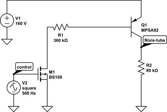
I'm multiplexing a pair of Nixie tubes. The high-side control is done with two pairs of transistors, MPSA92 high-voltage PNP to switch the 160V to the tubes, and a BS108 to control the base of the PNP:

schematic

simulate this circuit – Schematic created using CircuitLab

(R2 represents the Nixie tube).

The multiplexing is at 1000 Hz. However, I'm having some ghosting issues, and as seen on the 'scope, and in simulation, the problem is the turn off time of the PNP. It is quite slow, around 100-200µs.

I want to optimize this - I read about Baker clamps, but I was confused as there are no circuits with PNP transistors about them. I tried adding two diodes, one from collector to R1, and another from base to R1. However, this didn't improve anything at all! I'm not even sure there is such a thing as a PNP Baker clamp...

So, what are the possible options for fixing the turn-off delay?

anrieff
  • 5,199
  • 1
  • 27
  • 46

2 Answers2

5

Your control pulls the base of Q1 down, so you need to connect a pull-up resistor to it in order to bring it back up as quickly as possible. You will need to pick a value high enough that you don't bleed too much current through M1 when on (since every milliamp through the pull-up, R1, and M1 is wasted), but low enough so that the MPSA92 actually saturates with the voltage created by the divider created by the pull-up and R1 and M1.

Dave Tweed
  • 168,369
  • 17
  • 228
  • 393
Ignacio Vazquez-Abrams
  • 48,282
  • 4
  • 73
  • 102
  • 2
    Note that the pullup resistor will never have more than 0.7V across it. Most of the current will flow through the base of the PNP transistor. – Dave Tweed Dec 12 '13 at 12:48
  • 1
    Thanks! I tested with a 4.7k resistor and the problem is gone, both in the simulation, and in the actual hardware as well! – anrieff Dec 12 '13 at 16:15
2

When M1 is off, the base of Q1 is floating. You need some way to push it to a defined voltage. The simplest way is a base-emitter resistor. More complex ways would include putting a second transistor between M1-drain and Q1-emitter, and gating it opposite M1. Driving that new transistor would add a lot of parts, though. For most purposes, the pull-down resistor across Q1-BE should be sufficient.

The voltage across the new resistor will be ~.7V. It will also be stealing some of the current from the base, when M1 is on. So you may need to adjust R1 down to compensate and keep your base currents as high as you originally wanted.

As a general rule, I try to put a resistor across the base/emitter (or gate/source or gate/emitter) junction of all my transistors, just to force them into an off-state when not specifically driven on.

Stephen Collings
  • 17,373
  • 17
  • 92
  • 180