0

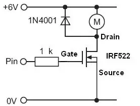
I want to utilize the below circuit to power a 12volt fan with the components listed. I'm concerned though because when I tried to do this with a resistor, the resistor got -very- hot. I understand why but if I utilize the transistor will it cause it to heat up? Does utilizing the transistor result in a more efficient use of power with less heat loss?

Thank you

Circuit diagram and tutorial from here: http://www.instructables.com/id/Use-Arduino-with-TIP120-transistor-to-control-moto/

enter image description here

stormist
  • 654
  • 1
  • 11
  • 20
  • 1
    Do you mean you used a resistor as a load instead of the motor? If so it's worth mentioning the resistance and power rating (probably was a 1/4 watt through hole I guess?) – PeterJ Dec 12 '13 at 06:33
  • 2
    @PeterJ I assume he used the resistor as a ballast resistor in series with the fan. Like you would with an led... And this is the second q in a week where the arduino tutorial linked shows a diode across the C-E pins of the TIP120 instead of the motor... – Passerby Dec 12 '13 at 06:48
  • See also http://electronics.stackexchange.com/q/93452/2191 – RedGrittyBrick Dec 12 '13 at 10:37

2 Answers2

1

The transistor is being used in the diagram provided as a switching mechanism to turn the fan on and off. From the data sheet, the Arduino will output 5v which will then allow the circuit from the 9v battery to be completed through the tip120 and power the motor. This method is much more efficient and will create much less heat than replacing the transistor with a resistor. The tip120 is rated for 60V and up to 5A to flow from the collector to emitter. The heat you are noticing is probably from a low ohm resistor that isn't rated for the watts. So, for example if you have a 9v and a 5ohm resistor, then you will have 1.8 amps of load and require a 16+ watt rated resistor. (I = V*R)

Here is a link to the TIP120 datasheet: http://www.adafruit.com/datasheets/TIP120.pdf

Hope this helps.

chipadmin
  • 11
  • 2
1

A mosfet would be a more efficient way as a switch (there is a but only if you intend to use fast switching PWM) because it has a very low resistance which translates to less voltage wasted as heat across the switching device and require no current from the microcontroller once it is turned on.

enter image description here

alexan_e
  • 11,070
  • 1
  • 28
  • 62
  • Why the gate resistor? – RedGrittyBrick Dec 12 '13 at 09:55
  • I prefer to have a resistor between external devices and the mcu pins especially since it doesn't have any side-efect for a simple switch (unlike when using PWM where it makes a big difference) but if the OP prefers to omit it then it will work fine too. – alexan_e Dec 12 '13 at 10:25