9

I need a circuit to measure the speed of sound in concrete to 1μs or better. This is for a school demonstration where students who study construction will use this circuit to measure the speed of sound in a sample of concrete to determine the quality of the concrete.

I have two 40kHz transducers: one to transmit the pulse and the other to detect the pulse at the other side of the concrete sample that is about 10cm thick.

I have PIC processors to generate the pulse and then detect the pulse.

However when I look at the many commercial Ultrasonic Concrete Testers on

http://www.alibaba.com/trade/search?sb=y&IndexArea=product_en&CatId=&SearchText=Ultrasonic+Concrete+Tester

It appears from their specifications that they are operating with khz transducers, not mhz. They do not mention frequencies higher then 200khz. Perhaps there is a limitation of good transmission of sound in concrete to khz frequencies because mhz frequencies are attenuated?

I have a requirement to build a VERY LOW COST student system, and I can only find inexpensive 40khz transducers. The Mhz transducers that I can find are much too expensive for my requirements.

It appears from the specifications for the commercial devices that they use pulses of 20us to 20ms and then wait for a receiver detection before sending another pulse. So the shortest pulse would be just a one complete 40khz sine wave and longer pulses would be several complete 40khz sine waves. Any distortion may be unimportant because they are not detecting a narrowband frequency, but just the first rise of the pulse from the receiver?

Does this make sense to anyone? I mean can anybody help me to solve this problem...

Thank you.

MarkU
  • 14,413
  • 1
  • 34
  • 53
FlaSh
  • 261
  • 1
  • 2
  • 10
  • 6
    Why don't you just use a dual trace scope and show it visually: this trace is the outgoing pulse; this trace is the pulse after passing through the concrete. You can measure the time delta off the screen. – Kaz Dec 11 '13 at 06:10
  • @Kaz hello sir.can you be more specific with little more explanation? – FlaSh Dec 11 '13 at 06:29
  • What kind of transducers? – alex.forencich Dec 11 '13 at 07:17
  • 1
    Just as an aside, _delay_ might be measured in microseconds but _speed_ is measured in meters per second. What you are measuring is delay, which can be converted to speed if you know the thickness of the concrete. – Joe Hass Dec 11 '13 at 12:22
  • The commercial machines appear to be for testing in situ with probes ten times further apart than your 10cm sample - would it be possible to use larger samples? – Pete Kirkham Dec 16 '13 at 13:16
  • This has to involve a shotgun of some type. Didn't anyone watch jurassic park? – Reactgular Jun 18 '14 at 18:31

5 Answers5

14

You don't need a circuit, I would use:

  • hammer (please see @hoosierEE comment, hammer may be overkill)
  • two small piezoelectric microphones (even a piezo speaker might work)
  • 2-channel digital oscilloscope

Glue / tape a piezo microphone to each side of the concrete. Connect piezo 1 to probe 1, the other to probe 2. Turn on both channels. Set the scope to trigger and hold off probe 1. Tap the concrete with the hammer next to piezo 1. The scope should trigger and then you can work out the difference between the initial and final pulses. Do multiple measurements to increase accuracy.

This will be much cheaper and less time consuming than other projects. As a bonus you will have a digital oscilloscope for other pracs such as motors, microphones, etc.

geometrikal
  • 4,921
  • 2
  • 23
  • 41
  • hmmm....you are right – FlaSh Dec 15 '13 at 06:13
  • 3
    Best answer here. Even a cheap scope will yield 1µs resolution. But I would say that instead of tapping `near` the trigger sensor, you should tap it directly. And maybe not with a hammer. :) – Alex Shroyer Dec 16 '13 at 14:02
  • 3
    A piezo buzzer can be made more sensitive by glue-ing a small weight on the membrane. – Johan.A Dec 17 '13 at 12:53
10

The speed of sound in concrete (according to uk.ask.com) is about 3400 m/s and therefore it will take sound about \$\dfrac{10 cm}{3400 m/s}\$ seconds to travel thru a 10 cm block of concrete - that's about 29\$\mu s\$.

A 40 kHz ultrasonic transducer wants to produce a sinewave at 40 kHz and so reception of what you believe should be a pulse is going to be subject to a lot of band-pass filtering (due to the 40 kHz transducer).

Apart from the sloppiness of the received signal, 40 kHz has a period of 25\$\mu s\$ and this is pretty much the length of time anticipated for sound to cross the concrete.

I believe you should be looking for transducers that have a massively higher resonant frequency, possibly as high as 10 MHz. This means you could apply a pulse that is only a few microseconds long and expect the edges of the pulse to be reliable for triggering counters in order to calculate time delay.

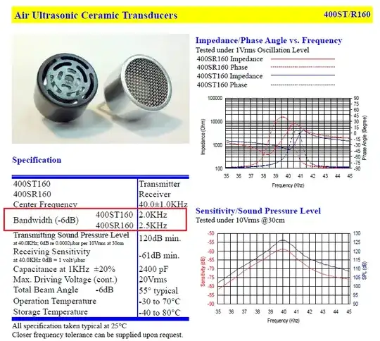
Here is the front page of a data sheet for a typical 40kHz ultrasound device: -

enter image description here

Note (in red box) the limited bandwidth - this means a pulse delivered to the device will produce a series of 40 kHz decaying ringing oscillations making sensible measurements a bit meaningless. Ditto when receiving a signal that might be a pulse.

Andy aka
  • 434,556
  • 28
  • 351
  • 777
  • thank you.. Can you make circuit layout I want help in circuit designing. – FlaSh Dec 11 '13 at 14:42
  • 5
    Unfortunately I don't come cheap even if there were a solution to your problem so that rules me out. It's not a case of making a circuit layout, you need to find the right ultrasound transducers - the ones I put in my answer are unsuitable and I think most 40kHz devices would also be unsuitable. You need devices that are resonant at a much higher frequency and, I note that you have not specified the device you wish to use therefore there is nothing that can be designed. – Andy aka Dec 11 '13 at 15:39
  • hmmm I agree Is there anything else that I can do instead of this..... – FlaSh Dec 11 '13 at 17:32
  • 1
    The "do nothing" route and hope for some more answers is not a bad approach but maybe you can raise another question with more detail about what you are precisely trying to measure in the concrete and see what folk come up with. Don't be specific about technology but do be specific about what makes good concrete from bad concrete. I'd be out of my depth trying to find an ultrasound solution that might work and leaving a possible new question open without half an idea of a technology might just get a better result. – Andy aka Dec 11 '13 at 18:43
  • Your analysis is very good. However when I look at the many commercial Ultrasonic Concrete Testers on http://www.alibaba.com/trade/search?fsb=y&IndexArea=product_en&CatId=&SearchText=Ultrasonic+Concrete+Tester It appears from their specifications that they are operating with khz transducers, not mhz. They do not mention frequencies higher then 200khz. Perhaps there is a limitation of good transmission of sound in concrete to khz frequencies because mhz frequencies are attenuated? – FlaSh Dec 13 '13 at 02:37
  • I have a requirement to build a VERY LOW COST student system, and I can only find inexpensive 40khz transducers. The Mhz transducers that I can find are much too expensive for my requirements. It appears from the specifications for the commercial devices that they use pulses of 20us to 20ms and then wait for a receiver detection before sending another pulse. So the shortest pulse would be just a one complete 40khz sine wave and longer pulses would be several complete 40khz sine waves. – FlaSh Dec 13 '13 at 02:39
  • Any distortion may be unimportant because they are not detecting a narrowband frequency, but just the first rise of the pulse from the receiver? Does this make sense to you? [sorry my comment is to long so I divided it into 3 parts] – FlaSh Dec 13 '13 at 02:39
  • You are doing the right research but without a definitive tech doc explaining the theory your only option is to set up a test. That's what I'd do. – Andy aka Dec 13 '13 at 11:36
8

Having worked in the industrial ultrasonics / NDT industry (although it was about 30 years ago :) ), I will try to add to the excellent advice you have already received.

Kaz makes a very good point that you should use an oscilloscope. This is potentially a very difficult project and you need to do the necessary R&D on the ultrasonics before you do too much circuit design.

There are a couple problems with the 40khz transducers that you may or may not be able to overcome. First, as pointed out by Andy aka, the time for the ultrasonics to pass through the concrete is not much different from the period of a 40khz wave. You MAY be able to overcome this by measuring the phase of the received signal relative to the transmitted signal. Second, your transducers were likely designed to be used in air. Due to the large density change when the ultrasonic enters and exits the concrete, you will lose most of your signal due to reflections. There may not be enough signal at the receiver. Since this is probably your simplest solution, it is worth testing with an oscilloscope.

Now things get more complex. You may need a couplant other than air to lessen the density miss-match. The couplant is the medium between the transducers and the material being tested. If you can immerse your sample, water is probably the best choice. If you can't immerse the sample, you could possibly use grease, petroleum jelly, mineral oil or some type of gel (I knew an Ultrasonics Applications Engineer who swore by Dippity-Do hair gel, but I don't think that is made any more). Your 40khz transducers may not be compatible with couplants other than air. The fluid couplant must replace all the air between the surface of the transducer and the sample being tested.

Andy aka also made the suggestion of higher frequency transducers. You should be aware that when you get into the Mhz range, you will definitely need a couplant other than air because ultrasonics at these frequencies attenuate very quickly in air. I have been away from the business and am no longer familiar with transducer prices or sources, but Google will help with that. Edit: From additional research, I see that frequencies suitable for concrete inspection typically fall in the range of 24kHz to 200kHz (see "Additional Research" below).

These higher frequency transducers are typically pulsed with a very fast high voltage pulse, typically maybe 300V or more in < 10ns (the faster the better). This is typically achieved with a fast SCR or, depending on voltage, circuits involving multiple SCRs in series. It's kind of like ringing a bell with a hammer.

Regarding volocity measurement: If your transducers are not in contact with the sample, you will need to subtract the time of travel through the couplant (water or air or whatever). The speed of sound in the couplant can vary due to various factors (such as temperature and contaminants), so for best accuracy you can measure it without the concrete in place by knowing the separation betweeen the transducers. You then need to subtract the concrete thickness from the transducer separation to determine the distance traveled through the couplant, then knowing the distance through the couplant and the velocity of sound through the couplant, you can calculate the time spent traveling through the couplant.

Regarding your sample clock and your velocity measurement resolution: A technique used in the ultrasonics industry to "effectively" increase the resolution is to use separate asynchronous clocks. One clock to derive the trigger for your transmission pulse, and a different clock for the time measurement. You then take the average of many measurements. Of course if you only need 1μs resolution in your timer, this will not be necessary.

I just found Ultrasonic pulse velocity test of concrete on youtube. There is not much technical information on the ultrasonics themselves, but it may provide some useful information. There are also links to other related videos. I see they use direct contact between the transducers and the concrete recommending grease or petroleum jelly as a couplant.

The NDT Resource Center also has much useful information on ultrasonic testing.

Edit ... Additional Research:

According to Ultrasonic Low-Frequency Short-Pulse Transducers with Dry Point Contact.Development and Application.:

The ultrasonic testing of concrete and ferroconcrete is possible on the frequencies not more the 150 - 200 kHz.

This paper goes on to discuss a "Dry Point Contact" (DPC) transducer which apparently uses no couplant.

I don't know if you will find anything useful here, but it is good to know alternative approaches.

THE IMPROVEMENT OF ULTRASONIC APPARATUS FOR THE ROUTINE INSPECTION OF CONCRETE is a very informative paper on the subject. Of particular interest are:

  • 2.3 Concrete and non-destructive inspection techniques (discusses various ultrasonic techniques and other alternative techniques)
  • 2.4 The PUNDIT test equipment (discusses the blocks making up the design of the ultrasonic equipment used as well as the transducers used)

This paper also discusses the frequencies used for concrete testing:

Different sizes of piezo electric element and case enable a range of transducer centre frequencies from 24kHz to 200kHz suitable for testing of concrete.

Final Note: Since the use of expensive transducers and high-voltage pulsers may be outside of your budget in both time and money for a student project, If you don't mind risking a couple transducers on some R&D, I would suggest that you make some attempts at modifying some inexpensive 40kHz air transducers to allow the use of a couplant. Use through-transmission with direct contact on the concrete (of a known thickness), and see if you can receive a signal. There is much help on the web regarding circuits for these transducers. You might start at How to Wire Up Ultrasonic Transducer
Tut
  • 4,195
  • 1
  • 21
  • 38
  • What about my plan to generate a series of pulses 40mz transducer and wait for replies?I can program a PIC to make one complete sine wave, then two, then three. For each pulse I would wait long enough for the reflections to die down.I have a 10cm long cylinder of brass that I have put transducers on each end.I know the speed of sound in brass so I can use this to calibrate my time delay between transmit and receive. So I can use my scope to see if I can measure a delay between the transmit start, and the rising pulse on receive. I have set up a 100x opamp amplifier on the receive tranducer. – FlaSh Dec 20 '13 at 17:59
  • 1
    That sounds like a good plan. The first thing is to be able to transmit and receive a signal. I think your main issue for calibration will be to account for whatever fixed delays you have due to both electronics and time for the ultrasonics to pass through the transistor faces and the couplant. The couplant should probably be as thin a layer as possible of grease or petroleum jelly with NO air. You could try measuring the delay by putting the transducer faces together, but it may work better to get a second calibration sample of a different known length of the identical material (say 5cm). – Tut Dec 20 '13 at 23:23
  • 1
    This will allow you to solve for the fixed transducer/electronics delay which you can then subtract from your time measurement when measuring the time through the concrete. You will need accurate measurements of the thickness of your concrete and for your calibration samples. – Tut Dec 20 '13 at 23:28
5

To simplify the project, I would not try to make an electronic mechanism for generating the pulse inside the concrete. Simply strike the concrete with a hard object. Use sensors only for picking up the sound.

Perhaps some kind of solenoid can be rigged to vibrate back and forth and tap at the concrete at so many times a second.

My comment already mentions the oscilloscope. Using that you may be able to get a time delta between two points on the concrete block.

Knowing the position of those two blocks and the position where the concrete is being struck, assuming an even speed of sound in every direction within the concrete, you can triangulate to obtain the speed.

I bet you that if you can tap the concrete, say, at least 30 times per second, you may be able to get a stable trace image with an inexpensive old analog scope. The sweep can be triggered by one channel (corresponding to the earlier transducer).

I'm wondering whether nothing more than an inexpensive electric engraver tool wouldn't just do the trick of generating sufficiently useful sonic signals in the concrete. These tools have sharp metallic point which vibrates. They are used like a pen in order to engrave identifying marks on objects (usually plastic or metal ones). The metallic chisel point is tapped at some multiple of line frequency like 120 Hz. When you move the tool too quickly, you can see the individual taps in the resulting trace on the material being engraved.

We don't need the pulses to arrive with a high frequency; just something high enough to get a stable visual display (yet low enough that all internal echoes within the concrete block can die down before the next pulse). We want the pulses individually have high frequency content: to have a sharp edge. When hard objects are struck, that tends to make sharp signals, with a frequency content into the ultrasonic range.

Kaz
  • 19,838
  • 1
  • 39
  • 82
  • Measuring the difference between two *inputs* is a good approach because it largely eliminates trying to subtract for things like the time it take for the stimulus to reach the concrete. More plainly, place one response transducer right next to the stimulus transducer. Then place a second response transducer 10 cm away. Read both responses and compare. Now you're using two identical ADCs that have the same latency, resolution, etc and so these factors can be largely ignored in calculations. So you just "strike the concrete with a hard object" and compare the two ADC responses. – squarewav Dec 12 '13 at 18:43
  • @ioplex Exactly. You don't have to account for the transmission delay, and the delays between the concrete and receiver cancel out if they are identical, which they can be expected to be. – Kaz Dec 13 '13 at 17:21
  • What about my plan to generate a series of pulses 40mz transducer and wait for replies?I can program a PIC to make one complete sine wave, then two, then three. For each pulse I would wait long enough for the reflections to die down.I have a 10cm long cylinder of brass that I have put transducers on each end.I know the speed of sound in brass so I can use this to calibrate my time delay between transmit and receive. So I can use my scope to see if I can measure a delay between the transmit start, and the rising pulse on receive. I have set up a 100x opamp amplifier on the receive tranducer. – FlaSh Dec 20 '13 at 18:00
3

I'm way out of my depth on this but I very much doubt that you can rely on the PIC for timing. Meaning if you just note the time, send the stimulus, receive the response and then compare the time, I can imagine that it might be very difficult to get an accurate reading. You need a circuit that will emit the stimulus, read the response and emit a value representative of the time passed all in one purely analog step. There is probably a clever circuit that does exactly that. What it is I have no idea. Look into old sonar circuits maybe. But I can guess that it would have something to do with the time it takes for a capacitor to discharge (or charge) through a resistor only because capacitors and inductors are the only passive components that have "memory". And you'll need a "sample and hold" circuit to save the otherwise fleeting output value. Note that an op amp may not necessarily be fast enough either. What is the speed of sound in concrete normally? My guess is it's quite a bit faster than the speed of sound in air. If an op amp is fast enough, you might charge a capacitor with the stimulus and compare that to the output of the response transducer. If you arrange for the two voltages to cross, the output of the op amp might somehow reflect the time between stimulus and response. Meaning if the time is short the output is "high" and if the time is longer, the capacitor has more time to discharge and the output is not as high.

One final suggestion, what you really want to do is measure the frequency response. Meaning take the FFT of the response. That is the electronic equivalent of tapping on something and listing to how it sounds. If it sounds dull, meaning it only has low frequencies, then it's not solid. But if transmits all frequencies it might be brittle. Or if it transmits one frequency really well it's resonating which might be bad or good, donno.

squarewav
  • 1,440
  • 1
  • 14
  • 33
  • 6
    You may want to revise your answer to be less humming-and-hawing. This seems more like a stream of consciousness rather than a well considered answer to a question. – Samuel Dec 11 '13 at 07:07