7

I am trying to get more precise temperature value from PT100 ( 2 wire ) sensor with Arduino.

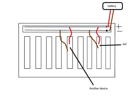
Here's how my circuit looks like :

Circuit

When the sensor is about 20 °C I get a value on A5 pin that is 432 and when the sensor is about 30 °C I get a value on A5 pin that is 440. As you can see this is a very small range ( 432 - 440 ).

I want a larger analog signal range, like from 100 to 1000.

Maybe I can somehow obtain the resistance of PT100 and with some math formula to get the temperature.

What can I do with my circuit to get a more precise temperature reading ?

jusaca
  • 8,749
  • 4
  • 36
  • 58
Muhamed Krlić
  • 329
  • 2
  • 4
  • 11

5 Answers5

8

You can not get more precise readings with an RTD directly connected to the A/D converter of the Arduino. To get more precise readings, you need to put the RTD into a bridge and use an instrumentation amplifier to develop a larger signal.

Dmitry Grigoryev
  • 25,576
  • 5
  • 45
  • 106
Joe Hass
  • 8,447
  • 1
  • 29
  • 41
4

You can use an external IC that takes care of reading the sensor and then get the result digitally, for example MAX31865

Maybe I could somehow obtain the resistance of PT100 and with some math formula get the temperature?

You can find resistance tables in internet , you can create a table in flash and use interpolation to calculate the temperature based on the resistance you get.

Daniel Grillo
  • 7,659
  • 18
  • 51
  • 69
alexan_e
  • 11,070
  • 1
  • 28
  • 62
4

First of all, If you want to get precision from a PT100, you have to use a 4 wires version not 2.

In a 4 wires version, one pair is used to "power" the PT100, the second one is used to measure the voltage drop in the PT100. That way the voltage drop in the cable is minimal: since V=RI and I is almost zero in the measuring pair, no voltage drop. That being said, since PT100 don't need specific wire, it is very easy to convert a 2 wires PT100 to a 4 wires PT100.

You also have to make sure the resistor used to measure the current going through the PT100 is a very precise one (like 0.01%). I also suspect you will need a better AD that the one you have in your Arduino.

Once you are sure you get precise enough data from your AD, then you will have to use PT100 tables to interpolate values. Newton method is easy to program and gives good results.

If you think all this is too complex to handle, then you should switch a to more easier temperature sensor. For instance a NTC would probably work directly on your Arduino, but you will get ~1° precision instead of 0.03°

martinm
  • 664
  • 4
  • 9
  • That's a great answer by you right there, clears things up. @alexan_e suggested that I use MAX31856 (RTD to Digital conv.) that has a precise A/D converter you are suggesting.. You deserved a vote up for a detailed explanation. Thank you. – Muhamed Krlić Dec 11 '13 at 23:13
  • Hi, I had a question about using 4 wires on arduino, where should the measuring pair connect to? one to Analog in, and the other? to GND? – Positivity Jan 10 '16 at 09:37
2

This topic might be a answer for you Measure resistance accurately with an arduino?

To calculate the temperature you can use this formula:

Resistance thermometer elements can be supplied which function up to 1000 °C. The relation between temperature and resistance is given by the Callendar-Van Dusen equation:

\$R_T = R_0 \left[ 1 + AT + BT^2 + CT^3 (T-100) \right] \; (-200\;{}^{\circ}\mathrm{C} < T < 0\;{}^{\circ}\mathrm{C}),\$ \$R_T = R_0 \left[ 1 + AT + BT^2 \right] \; (0\;{}^{\circ}\mathrm{C} \leq T < 850\;{}^{\circ}\mathrm{C}).\$

Here, \$R_T\$ is the resistance at temperature \$T\$, \$R_0\$ is the resistance at \$0 °C\$, and the constants (for an \$\alpha=0.00385\$ platinum RTD) are:

\$A = 3.9083 \times 10^{-3} \; {}^{\circ}\mathrm{C}^{-1}\$

\$B = -5.775 \times 10^{-7} \; {}^{\circ}\mathrm{C}^{-2}\$

\$C = -4.183 \times 10^{-12} \; {}^{\circ}\mathrm{C}^{-4}.\$

Source: English Wikipedia (http://en.wikipedia.org/wiki/Resistance_thermometer)

I hope it was helpful.

kimliv
  • 628
  • 3
  • 14
  • 29
0

I think you need to feed between 7 V and 12 V to the VIN pin of your Arduino and use the AREF pin for one side of the PT100 and the other one to analog in. That might help get a consistent reading but you might still have to do a 4 wire measurement to get it precise.

4 wire kelvin resistance measurement tutorial has a good explanation for 4 wire measurement. You probably sussed it already though.

Edit You hook the AREF to arduino 5v or 3.3v and the pt100 from the same voltage to a suitable analog input pin on the arduino. The linear voltage regulators on the arduino board are much more stable than your USB power brick and so will give better accuracy. Arduino Basics (Analog Reference)