-2

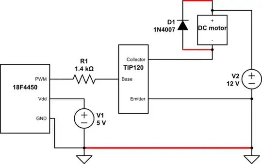
I'm trying to achieve this. He's using a darlington transistor, so I started looking for an appropriate circuit. I've made that, with a TIP120, using a 1k4 resistor (instead of 1k) and a 1N4007 diode (instead of 1N4004). But I do not believe that those two changes should make too big of a difference. I use a PIC 18F4450 to generate the PWM signal.

However it seems to be low on current. Because it does creates a high pitch noise, but does not move. My 12V power supply can provide up to 20A so that should be enough (by far). I also tried different PWM frequencies, including the 500Hz value that is used in the YT video. I get different noise pitches, but again no movement.

If I connect the valve directly to the power supply it opens all the way, so the valve itself is also working fine.

What am I doing wrong/not seeing?

schematic

simulate this circuit – Schematic created using CircuitLab

JYelton
  • 32,302
  • 33
  • 134
  • 249
Felix
  • 27
  • 1
  • 6
  • Can you post a schematic? PWM alone likely won't control this like you want, but need PID with position feedback. – Erik Friesen Dec 10 '13 at 13:53
  • I understand, it needs to become a closed loop system. But I though I get the thing moving first... Let me add a schematic, one moment – Felix Dec 10 '13 at 13:54
  • Use real grown-up symbols for electronic parts. We shouldn't have to decipher the schematic to see the circuit. This mess needs to be re-drawn. – Olin Lathrop Dec 10 '13 at 14:17
  • 1
    See http://electronics.stackexchange.com/q/28251/2191 ... Also, do you have two unconnected grounds there? – RedGrittyBrick Dec 10 '13 at 14:20
  • Well I got it moving allright... A simple oversight... I forgot (as you can see in the schematic) to wire the GND of the PIC to the GND of the driver circuit (TIP120 emitter). For clarity I will redraw the schematic as soon as I can properly sit down for it and take the time. Until then, please hold your horses. – Felix Dec 10 '13 at 14:23
  • 1
    Shouldn't the diode go across the motor, rather than across the switch? – user28910 Dec 10 '13 at 16:19
  • 1
    Your PSU may be 20A but the TIP120 is 5A max, and even then it'll be getting quite warm as it's a darlington. However, I don't think that's your issue, just issues down the line... – John U Dec 10 '13 at 16:26

1 Answers1

3

As OP has noted in the comments, they forgot to connect the two grounds together.

schematic

simulate this circuit – Schematic created using CircuitLab

Additionally, they have the diode in the wrong place. The correct place is directly across the two terminals of the motor.

Finally, to calculate the Collector Current, (5v Source - 1.4v* VBE Diode Drop) / 1400Ω = 0.00257 Amp or 2.57 mA. The TIP120 has a minimum hfe or gain of 1000, so 2.57mA * 1000 = 2.57 Amps at the collector. The motor show draw about 2.5A or less, at stall, ideally.

*(1.4v Diode Drop because this is a Darlington NPN Transistor)

Passerby
  • 72,580
  • 7
  • 90
  • 202