I'm working on a design, and this will be my first attempt at a buck-boost regulator.
I need the output to be variable because my application calls for different voltages under certain conditions.
The buck-boost regulator I'm considering is the LT8705
Most of the reference designs I've seen have used either a fixed output, or in some cases, I've seen where a potentiometer was added but never a digital one.
I haven't yet decided on specific digital pot, but let's assume I decide to use this MCP4021/2/3/4 to replace the 392k and 10k resistors connected to the FBOUT pin on the right side of the image shown above. I haven't calculated what exact resistors I'll need so for the purpose of this question, assume that the digital pot's resistance is in range.
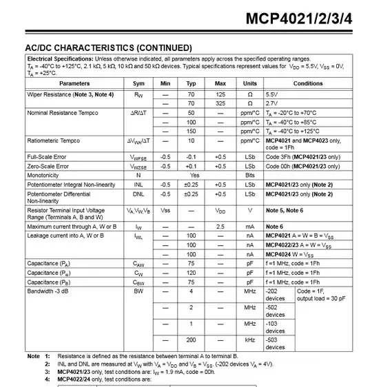
Max current through the resistors is 2.5mA. My max output voltage would be 28V. If I set my pot to be greater than 11.2kohm, the current would be < 2.5mA through it.
$$ R_{min}= \frac {28V_{max}}{2.5mA_{max}} = 11.2k\Omega$$
If this is true, then my next question is what considerations should I be aware from the following snippet from the datasheet
..set by an external feedback resistive divider carefully placed across the output capacitor.
What would 'carefully placed' entail ? Would placing this IC near the regulator potential disrupt its behaviour ? Any additional feedback would be appreciated.
Thanks!
