4

I'm working with an infrared emitter/detector system based on an Osram SFH 4545 IR LED collimated through a 40mm dia, 120mm fl lens and a sensor array based on three separate sets of three Vishay TSOP 34856's all running a 56kHz signal. Both emitter and detector are designed to mounted on a wide variety of fully mobile objects and so cannot be physically connected.

The issue is the mobile elements mounting the sensor arrays are typically much larger in terms of surface area then the detectors can cover, especially considering the number of components used. Also, by design the sensors must be exposed during a highly physical process thus requiring additional protection and maintenance.

Would it be possible to use fiber optic lines as a light pipe to bring the IR signal to the sensor array? I am imagining arranging multiple lines over a broad area of the target element, thus increasing the area each array can cover and also allowing the delicate sensor components to be moved to a more protected location. Ideally, I would like to be able to utilize the same detectors or at least one with similar parameters so as to avoid any redesign or reprogramming.

If this is possible, what type of cable would be required? How would the ir signal be collected at each cable? I can't imagine that you would have raw cable ends sticking out everywhere, but I can't seem to find any termination components that aren't designed to physically connect to a light source. I've researched this fairly thoroughly via Google and several other message boards and haven't found the information I need. My team and I are firmly in the DIY camp and so our knowledge base is deep only in specific areas. Fiber optics is not one of them. Any help would be appreciated.

  • 1
    @krb686: comments are for helping the OP improve their question, not for stream-of-consciousness drafting of an answer. I think you should cut&paste that lot into an answer and delete the sequence of comments. Just my 0.02 worth. – RedGrittyBrick Dec 05 '13 at 16:56
  • Very good suggestions – krb686 Dec 05 '13 at 17:04
  • What you're asking for can be done but might cost a bit to optimize for your situation. Can you mention your budget (order of magnitude -- like $10 or $10,000) for this project? In the meantime, you might try a web search for "optical fiber bundle". Or if you don't need a flexible connection, "light pipe". – The Photon Dec 05 '13 at 17:17

3 Answers3

2

So you just want to use fiber optics to expand the coverage area of the sensors. It's entirely possible for IR to travel through fiber optic cables, it just depends on the type of cable, and the transmission wavelength. Have a look at this, specifically the diagram showing scattering and absorbtion by wavelength in fiber optic cable.

Understanding Wavelengths in Fiber Optics

enter image description here

And as they say on that page, the prime wavelengths are 850, 1300, and 1550, because they fall between the absorption bands, and it seems like 1550 > 1300 > 850 because of the scattering curve. Fiber optics are used with IR LEDs for example in products like this:

enter image description here

Fiber-Optic Coupled IR LEDs

However that's obviously different from what you're doing, since your IR source isn't directly at one end. I imagine it will come down to is the IR detector sensitive enough, and that'll depend on how much of the light makes it into the cable, or how far apart is the cable and LED.

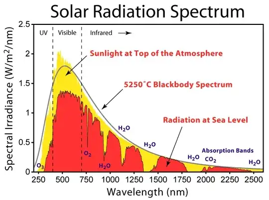
And it looks like your detector is sensitive from 850 - 1050nm, and your LED is 940nm so that's good, but if you're going to be using this during the day, you have to worry about solar irradiance, and atmospheric absorption. It looks like there's about 0.75 W/m^2 at 940nm of irradiance, and the absorption band is around one of those plateaus:

enter image description here

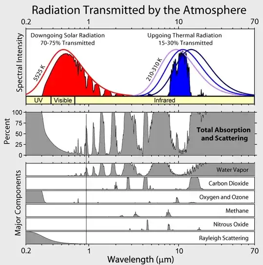
Or on this image, it's the first peak above 50% from the left, at about 65%, mostly due to water vapor:

enter image description here

So since I don't actually know whether you plan to use this in broad daylight or not, I'd say if it's a night only device, go for it. If not, it might still be possible, but it might be difficult. If you try it out and it doesn't work, there are 3 things I can think of that might help:

  1. Get a more powerful IR LED -It looks like you already have the most powerful IR at 940nm at least on digi-key, but it couldn't hurt to look around.
  2. Get more sensitive detectors
  3. Move to a different wavelength. --I actually have some IR LEDs from OSRAM as well. Your 4545 has a peak of 500mW/sr radiant intensity. The ones I have are the 4751, which peaks at 1250 mW/sr. Those look to be discontinued, but they do have the 4750, which has essentially the same specs. 1250 mW/sr, at a wavelength of 850nm
krb686
  • 1,215
  • 13
  • 23
  • I appreciate the graphs. That gives me a better understanding of what I need to look for in terms of wl. They will be used both in and out of direct sun. The epoxy block around the TSOP assembly is designed to mitigate intereference somewhat. Good info on the LED's. 850nm is within the range we can work with without serious modification. Any suggestions on detectors? – Rampant Mongoose Dec 05 '13 at 18:39
  • Here's a phototransistor with peak sensitivity at 850nm : http://www.vishay.com/docs/81526/bpw76.pdf Only think I don't like about that particular one is that it still has some sensitivity dipping into visible light. You could opt for a IR-pass filter. These have very steep curves. http://www.maxmax.com/axnitefilters.htm Something like the X-nite 780 or X-nite 830 could deal with that problem – krb686 Dec 05 '13 at 18:49
1

Back in 1972 I had fibre optic cables produced (by a sceptical IR detector manufacturer) to attach onto the lens of several industrial IR detectors, these detectors being used to monitor the passage of 'red hot' steel blooms at a continuous casting plant. Although the IR detectors were water cooled and 'set' at maximum sensitivity, they originally still had to be installed very near the passing blooms to operate effectively. However, this original arrangement resulted in a very high detector failure rate. The fibre optic cables, which were each about 1 metre in length and about 5mm in diameter (within a flexible outer casing), were initially manufactured with high temperature 'ends' to allow them each to be placed near the blooms, with the associated IR detectors moved back to a 'safe' cooler location. The modified system worked extremely well with the fibre optic cables moved even further away from the blooms. Because of this, later fibre optic cables did not have to be heat resistant like the pilot devices and were cheaper to procure.

T E Jermy
  • 11
  • 1
0

WRT krb686's mass of graphs, please note that there are newer fibers with considerably better transmission than the first image. You may be able to find something suited to your wavelength of interest if you shop the specialty suppliers, but you'll find it cheaper to use standard telecommunications fiber in general. You're at 940nm on the LED source, so most of the 62.5 or 50 um multimode fiber will probably work fine. To get more light, with some possible forms of degradation that MAY or MAY NOT matter to your application, you could look at some of the older "large-core" fibers, since you seem to be looking at relatively short fibers. They lack fancy features that matter to modern telcom, but they are bigger "pipe" with 100 or 200 um cores (in glass, step index.) I think your wavelength will aso work in typical "plastic fiber optics" which are up in the 1mm core size, and cheap.

As for how you get the light in, you may be able to DIY but it's a generally expensive area to play in. "ball end lensing" (possibly "self-lensing" or something like that to be more generic) of fibers is the/a typical approach to get a signal coupled into a fiber - you essentially melt the end of the fiber and let it make its own lens. Trick is, this is usually done with a fiber optic splicer, and those cost more than my car...OK, it's not that new of a car, but still. 2 in the image is a ball-lens - they are showing other shapes as well, used for some other purposes.

Some lensed fibers

Here is a link to a "not just for lighting grade" POF - 960um/1000um TLC POF page which is available for ~45 cents/meter (less in bulk, I'm sure)

Ecnerwal
  • 5,594
  • 17
  • 24
  • Very helpful. That gives me some new lines of inquiry, especially the mm fiber. Of course, the cheaper the better. This aspect is purely speculative protoyping at this point. My initial research seemed to indicate that plastic fiber tended to absorb in the IR, but I will start looking at specialty manufacturers. Fortunately most offer patch cables that are long enough for my purposes. Ball lensing looks like the way to go. I found some FiO tapers and faceplates that would be just the thing, but they are monstrously expensive. – Rampant Mongoose Dec 05 '13 at 18:56
  • If your wavelegth of interest is 940nm (ie, it's not shifted, or not shifted very far) PMMA looks to be flat (similar loss to visible band) beyond 1000 nm. Of course, it still may be too much, depending on length required. – Ecnerwal Dec 05 '13 at 19:09
  • That particular LED only shifts slightly up to 950nm. I see what you mean about PMMA fiber, great call. Transmission % stays right around 90, but the attenuation rate is literally off the chart past 800nm. I wouldn't need anything longer than a meter, so that shouldn't be a serious issue. Plus PMMA is cheap enough to do some hands on testing with, which is how we like to do things 'round here. I think I have enough information to at least do some preliminary proof of concept work. Thanks! – Rampant Mongoose Dec 05 '13 at 20:32