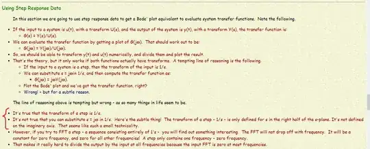
Why we can't substitute s for jw in the case of a step function (1/s)?
It is true that the region of convergence (ROC) for the Laplace transform of the unit step is \$\Re(s)\gt0\$.
So, setting \$s = 0 + j \omega\$ and calling that the Fourier transform isn't justifiable even if "it works" in some cases.
But, on the website, the context suddenly changes from the Laplace transform of an aperiodic signal to the DFT. That's quite a chasm to jump over!
- First, we've made a jump from continuous time to discrete time
- Second, we've made a jump from aperiodic to periodic
The author writes:
However, if you try to FFT a step
Whoa! Why on earth would you try to do that? Recall that the DFT is essentially the discrete time version of the Fourier series which is for periodic functions.
One should no more try to find the DFT of \$u[n]\$ than one should try to find the Fourier series for \$u(t)\$.
Since both \$u[n]\$ and \$u(t)\$ are aperiodic, the appropriate transforms are the DTFT and Fourier transform respectively.
Remember, when finding the Fourier series, the Fourier coefficients are found by integrating over a period. What is the period of a unit step function? Is it surprising that applying a transform for periodic functions gives odd results when carelessly applied to an aperiodic function?
However, you will find that the DTFT of \$u[n]\$ exists (in the sense of generalized functions) and is:
$$X(\omega) = \frac{1}{1-e^{-i \omega}} + \pi \cdot \delta (\omega)$$
Finally, the title question:
Why we can't use step function to identify system's transfer function
We can. However, the context is crucial and the context of the linked website is numerical methods with the FFT.
In the discrete time domain, assuming zero initial conditions and an input that starts with one and is an unending sequence of 1's thereafter, the associated unending output sequence is the step response of the system we'll call \$s[n]\$.
The DTFT of this unending output sequence would be a continuous function of frequency \$S(\omega)\$, \$-\pi \lt \omega \le \pi\$, and would be the step response in the frequency domain.
Thus, the transfer function is:
$$H(\omega) = \dfrac{S(\omega)}{X(\omega)}$$
Now, if you wish to do an FFT of the output sequence, you'll use only a portion, the portion from \$s[0]\$ through \$s[N-1]\$ for some \$N\$.
Essentially, this is equivalent to discarding the rest of the sequence for \$n \ge N\$ and making the output sequence periodic with period \$N\$.
Why? If we take the first \$N\$ numbers in the sequence and periodically "block" copy this before and after to form a periodic sequence, the DTFT of this periodic sequence would become a weighted impulse train with the weights given by the FFT (up to some normalization constant).
But, for a stable system, the output sequence is periodic only if the input sequence is periodic and \$u[n]\$ is not periodic.
Thus, an FFT of some portion of an output sequence cannot represent the step response of a system.
However, there are "tricks" that The Photon mentions in his answer but these are beyond the scope of this answer. Feel free to ask a follow-up question but it might be better to ask on the DSP sister site.