1

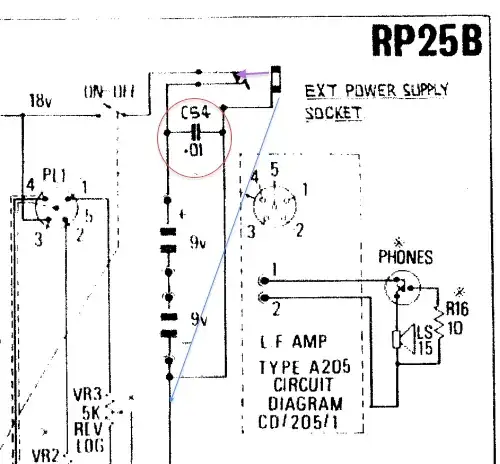
I am transforming an old battery-only radio so I can connect it through a DC input. I found an earlier model diagram that includes the DC input (picture attached). I have connected a 18 V DC source (Switching Power Supply from Maplin). However, even using the 0.01 uF capacitor I still have quite a strong hum. What else could I do to further smooth the input? Would it make sense to connect more capacitors in parallel?

I have tried to find a way to calculate the decoupling capacitance or even simulate it without success.

Here is a sample of the hum I'm hearing (I'm setting the volume up and down so the hum can be identified):

http://jorgepena.net46.net/AudioRecording.mov

enter image description here

UPDATE

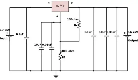
As suggested I have implemented the circuit shown below. It reduces the hum to about half of its volume without reducing the music volume. Is there anything else I could do to further reduce the high frequency hum? Would it make sense to decrease the voltage to 15.5 V or to add more capacitors?

enter image description here

zom-pro
  • 269
  • 1
  • 3
  • 9
  • 1
    Looks like you forgot to attach a picture. – jpwr Dec 04 '13 at 21:01
  • That is a coupling capacitor used to drive higher frequency transients to ground. – Shabab Dec 04 '13 at 21:05
  • 1
    For more about decoupling capacitors see http://electronics.stackexchange.com/questions/2272/what-is-a-decoupling-capacitor-and-how-do-i-know-if-i-need-one/ or http://electronics.stackexchange.com/questions/5830/are-decoupling-capacitors-needed-with-battery-power/ – David Dec 04 '13 at 21:12
  • Do you know what size that capacitor is? Is it 0.01 f? I have seen than in some other sections of the circuit the size is specified, e.g. 270 pf – zom-pro Dec 27 '13 at 16:15
  • I just figure it out that it's 0.01uF (just in case someone wanted to know...) – zom-pro Dec 27 '13 at 16:22
  • When you say hum, do you mean 60/50 hz hum, or switch-mode (e.g. high-frequency) buzz? – Connor Wolf Feb 10 '14 at 06:19
  • I uploaded an example of the hum. It seems to be a high-frequency hum rather than a 50-60 hz one. – zom-pro Mar 01 '14 at 16:46

1 Answers1

2

The noise you're hearing is most likely coming from the switching frequency of the power supply; perhaps mixed down by the radio's Superhet receiver.

In situations like this, where you want a low noise output from a switching power supply, extra capacitors are not your answer (although they help). The problem is that the ear has a very high dynamic range to audio. So even if you filter it with decoupling capacitors it may still be audible.

The answer is to use a linear regulator such as an LDO to step the 18V from the switcher down to a lower Voltage (say 16V). This step down "slices off" the hum sitting on top of the 18V DC.

Here's an example of an LDO from LTC with a 36V input range and adjustable output up to 36V.

akellyirl
  • 4,117
  • 1
  • 16
  • 30
  • Would something like this do the trick? http://www.circuitstoday.com/few-lm317-voltage-regulator-circuits – zom-pro Mar 03 '14 at 21:37
  • 1
    Your on the right track but the reason I suggested an LDO is because you'd like a low dropout Voltage. See Figure 4 here: http://www.fairchildsemi.com/ds/LM/LM317.pdf If you regulate the output to 16V (for example) and the dropout Voltage is 0.5V then the input Voltage must be > 16V + 0.5V = 16.5V for the output to be maintained at the regulated 16V. At Vin < 16.5V the Vout = Vin -0.5V. The LM317 droput Voltage can be as much as 2.5V, so your radio would have to work well at 18V - 2.5V = 15.5V and you need say 2V for battery discharge = 13.5V. That means you would need to regulate to ~ 13V. – akellyirl Mar 04 '14 at 10:18
  • I get the dropout Voltage, but why do I need to take into account the battery discharge? (considering I'm using the switching power supply connected to AC). The measured voltage out of the source is about 17.8V. Originally, the radio uses two PP9 batteries which drop from 9V to around 7V. So my bet is that the radio should work well at around 14-15V giving room for the dropout voltage (17.8-2.5 = 15.3V approximately) – zom-pro Mar 04 '14 at 11:28
  • You're right. I was considering that you might still need to run it off a battery sometimes. Make sure to add the Cadj capacitor to maximise ripple rejection. – akellyirl Mar 04 '14 at 11:32
  • One last detail before building the prototype. What type of capacitors should I use? Can I use ceramic for both or is it better to use ceramic for the input (0.1 uF) and electrolytic for the output (10 uF)? – zom-pro Mar 05 '14 at 09:41
  • I'd use Ceramic for the input and Tantalum or Electrolytic for the 10uF and I'd put another 0.1uF ceramic in parallel with the 10uF to provide high frequency decoupling. Most important is to add 10uF across R1 (between pin1 and ground); and add 0.1uF in parallel with that too. – akellyirl Mar 05 '14 at 10:09
  • I built the prototype. I have updated the original question including your suggestion. – zom-pro Mar 10 '14 at 21:11
  • Finally the answer as a combination of what you said and changing the cheap Maplin psu for an old 19V computer charger. There is absolutely no hum now. Thanks! – zom-pro Mar 19 '14 at 09:14