4

I am working on an art installation and plan to use a number of these small circuits to make sounds, to sense sound/vibration and also to move the device (using a triangle wave output).

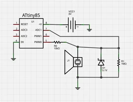
This link gives examples of input and output using the piezo. I have crudely mashed the circuits together into one. Would this work? Or do I need some more components, eg diode protection on the output.

The objective is to create a small circuit with the minimum of parts that can be experimented with as a cell in a kind of physical automaton.

Circuit

Rob
  • 285
  • 2
  • 8
  • 1
    At least add a decoupling cap (100nF) across the AVR's power pins, with leads as short as possible to the ciontroller. – jippie Dec 04 '13 at 07:42

1 Answers1

6
  • Add a decoupling cap (100nF) across the AVR's power pins, with leads as short as possible to the ciontroller;
  • For the zener diode use a voltage close, preferably slightly lower to the battery voltage. The trigger threshold of the input is ½ Vcc, so you definitely want the zener voltage higher than that;
  • Did you actually check the sound output volume level with the 10k resistor?
  • You probably want to turn the PWM pin in INPUT mode (high impedance) while sensing the input voltage, to not unnecessarily load the already weak piezo signal;
  • As you need to turn the output pin into input mode for sensing anyway, you can probably use just a single GPIO pin for both functions (saves parasitic capacity and leakage current).
jippie
  • 33,033
  • 16
  • 93
  • 160
  • Thanks @jippie, will check sound volume with breadboard, and it's nice you thought about using only one pin - that had crossed my mind, but I thought it might make things more complicated electrically. Hopefully I can make the construction very compact and simple. – Rob Dec 04 '13 at 08:20