15

I've been playing around with an Arduino for a while now, and while I know just enough about simple circuits to get little projects up and running, I still don't know enough to figure out what's going on in all but the simplest of circuits.

I've read a few books on electronics and a handful of online articles, and while I think I understand how voltage, current, resistors, capacitors and other components work; when I see a schematic with lots of them in, I don't know what's going on where.

In a bit to finally get to grips with it, I bought a 300-in-1 Electronics Project Set, however it seems to jump from "Here is a circuit with two resistors in parallel" to things more complex, without explaining how it works.

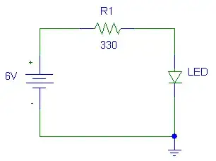
For example, it shows a simple battery->resistor->LED circuit, but shows that if you wire a button up in parallel with the LED, pressing the button turns the LED off.

I get that the current must be travelling through the path of least resistance, but I don't understand why it doesn't travel through both.

I'm taught that wiring two resistors up in parallel causes the current to flow through both, and so more current flows in the circuit. I've also tried replacing the button in the circuit above with resistors of varying values, and as I suspected, a high value resistor doesn't affect the bulb at all, but lower values start to dim the bulb.

I'm not sure how to apply the E = IR equation to all of this.

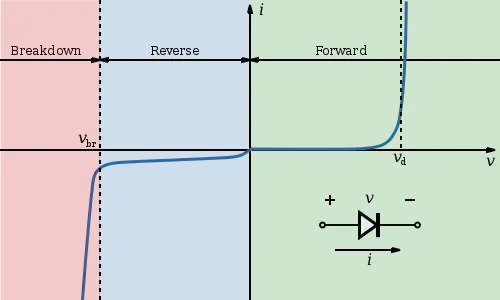
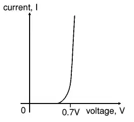
Also, how much resistance does an LED have? I tried measuring it with my multimeter, but it wouldn't give a reading.

Sorry if I've waffled on loads here, but I'm trying to paint a picture of what I think I understand and what I want to understand. Not sure I've achieved that!

Oh yeah, and expect lots more of this as I delve deeper into my 300-in-1 project kit!

clabacchio
  • 13,481
  • 4
  • 40
  • 80
littlecharva
  • 564
  • 1
  • 6
  • 12
  • 4
    If you have the time and the interest, it may be of use to go through some of the early lecture material for electrical and computer engineering found at MIT's opencourseware site: http://ocw.mit.edu/courses/electrical-engineering-and-computer-science/ . – pfyon Jan 19 '11 at 19:47
  • 1
    There's also http://www.allaboutcircuits.com/ which is interesting. – AndrejaKo Jan 19 '11 at 19:49
  • 2
    Since you are starting, I'd also recommend getting familiar with a SPICE program like the free LTSpiceIV, which will allow you to simulate circuits and experiment, without having to go through all the effort of wiring and unwiring. – whatsisname Jan 19 '11 at 21:47
  • Thanks guys, I'll try those sites, and give a Spice program a whirl. – littlecharva Jan 20 '11 at 09:03

4 Answers4

9

You cannot directly apply E=IR to this because the LED is a diode, which is a nonlinear device.

Simplified: a diode will not conduct current unless sufficient, correct-polarity voltage is present across its terminals to forward-bias it.

The resistance of the switch shorting the diode out is very small, so the voltage generated across it is also very small, certainly many orders of magnitude too small to forward bias the diode.

If you replace the switch with a resistor, things can change. Imagine the LED is out of the circuit. If the resistor limits the current sufficiently to develop a voltage drop across it that is equal to or greater than the forward-bias requirement of the LED, once you put the LED in the circuit you will see that the LED will be on dimly as you observed. There is current being 'shared' by the LED and the resistor- you will observe that the voltage across the resistor in parallel with the diode is 'clamped' by the diode.

Diodes are not intrinsically resistive like resistors are. Their resistance is extremely small - this is why an LED circuit requires a series resistor - to provide resistance which limits the current and protects the diode from failing.

See the Wikipedia article on diodes.

Kevin Vermeer
  • 19,989
  • 8
  • 57
  • 102
Adam Lawrence
  • 32,921
  • 3
  • 58
  • 110
8

Well, I'm studying electrical engineering right now and I can tell you that such jumps as you described take around two years of lectures at my university.

First thing which is important is to know which elements are passive and which are active. Then you need to know which elements are linear and which aren't. Next step is to get equivalent schematics for elements which you have and to see how they behave.

For example, let's take the switch. In off state, it functions as an open circuit, while in on state it functions as short circuit. Next, if you have sensitive equipment, you'll be able to notice that the switch isn't actually short circuit because it has some resistance, but that it's very low. Now let's take a look at the diode. Diode isn't linear component, so it doesn't have resistance in the classical sense in which for example resistors have. Instead there's the V-I curve of the diode. On a resistor, it's a linear function and we can use resistance as its characteristic, but on diode, it looks exponential.

diode curve from wikipedia

As you can see from the image, certain voltage is needed for diode to start working properly and when you trigger the switch, that voltage disappears. That means, that the "resistance" of the diode just became huge. To get a feeling for this, use the parallel resistor calculation for say 1 mΩ resistor and 1MΩ resistor and take a look how much current goes through each of them. This is the way the circuit you mentioned behaves.

AndrejaKo
  • 23,261
  • 25
  • 110
  • 186
  • Ah, I think I get this now. The closed switch and the first resistor act like a voltage divider, and as the switch has almost no resistance, the resistor consumes most of the voltage, so there isn't enough to trigger the LED - correct? So replacing the switch with a suitable resistor divides the voltage differently, so there is enough to trigger the LED, but because the voltage is still divided, the LED is receiving less voltage and so doesn't glow as brightly? – littlecharva Jan 20 '11 at 09:04
  • So if I were to replace the LED with a bulb, and leave the switch in place, some of the current would flow through the bulb (unlike the LED), but the voltage would still be too low to make it glow? – littlecharva Jan 20 '11 at 09:04
  • @littlecharva I think that's right, but the "some current" part is going to be really really small. For example, I've seen a light bulb which has working resistance of 1000 Ω, while one of the switches I have shows resistance of around 0.1 Ω. So if we put for example, 9 V across the closed switch and bulb connected in parallel, we'd get 90 A through the switch and 9 mA through the bulb, assuming the bulb manages to get into high resistance state. – AndrejaKo Jan 20 '11 at 11:38
4

Ordinary resistors are linear devices; if 10V over a resistor results in a 1mA current, then 20V will give you 2mA. That's easy enough, but few components are that simple.
A LED (or any diode for that matter) for instance doesn't behave like that.

enter image description here

If you put a low voltage like 100mV over a diode there will hardly be any current. If you slowly increase the voltage you'll see that around 0.7V the current begins to flow, to reach a high value very soon, see graph. We can see that the voltage over the diode is more or less constant. The 0.7V is for a common silicon diode, for LEDs this voltage will be higher, mainly depending on the color, but the graph is basically the same. Because the current will increase so suddenly to a value that will destroy the LED you have to use a current-limiting resistor. The increase in current will be sudden, but not immediate; the line in the graph is not quite vertical. That's because the LED has also a small resistance, but this is too small to limit the current to a safe value. So what does this mean in a circuit?

enter image description here

Two of the basic things in circuits (apart from Ohm's Law) are Kirchhoff's Laws, there's a Kirchhoff's Voltage Law, aka KVL, and a Kirchhoff's Current Law (KCL). We forget KCL for a moment and have a look at KVL, the voltage law. This says that the sum of the voltages in any closed loop is zero. You choose a direction in which you go through the loop. We choose clockwise. The power supply's voltage is usually chosen as positive, going clockwise we go from negative to positive. Then the voltages over the resistor and LED are negative, because we encounter positive first. Then Kirchhoff says: \$V_{BAT} - V_{R} - V_{LED} = 0\$, or \$V_{BAT} = V_{R} + V_{LED}\$. Let's assume the LED has a voltage of 2V. Then we can calculate \$V_{R} = V_{BAT} - V_{LED} = 6V - 2V = 4V\$, and the current through the circuit \$I = \frac{V_{R}}{R} = \frac{4V}{330 \Omega} = 12mA\$.

What happens if we place a switch parallel to the LED? If the switch is closed it has zero resistance, and according to Ohm's Law it will have zero voltage over it. And still according to Ohm zero voltage over any resistance means zero current, so given the LED's resistance there will flow no current through it.

stevenvh
  • 145,145
  • 21
  • 455
  • 667
2

A diode is not characterized by an impedance, whereas resistors, capacitors, and inductors can be cast in the same electrical mold - each having a "resistance" (that potentially varies with respect to the "frequency" of the applied voltage signal).

A diode, on the other, hand draws an amount of current that depends non-linearly on the voltage applied across its terminals. A switch in parallel with it, when closed effectively makes the voltage drop across it zero, and it therefore does not conduct current.

Incidentally, and for a different reason, you would observe a similar phenomenon if you replaced the LED with a resistor. Pushing the switch is like putting a 0-ohm (or very small anyway) resistor in parallel with it. Almost all of the current will flow through the short circuit.

Edit

In response to the addendum question in the comment on my response. There are many ways to show this, but lets say you have:

                        R_1
                   +---^v^v^----+
          R_x      |            |      R_y
   Vcc---^v^v^-----+            +-----^v^v^----GND
               V_x |    R_2     | V_y
                   +---^v^v^----+

Let Delta_V = V_x - V_y

We know that Delta_V is the drop across R_1 and R_2 (i.e. the drop across R_1 is the same as the drop across R_2 is equal to Delta_V). That voltage drop implies a current through both resistors. Namely:

                        R_1
                   +---^v^v^----+
          R_x      |    -->     |      R_y
   Vcc---^v^v^-----+    i_1     +-----^v^v^----GND
          -->      |    R_2     | 
        i_total    +---^v^v^----+
                        -->
                        i_2

Delta_V = i_1 * R_1
Delta_V = i_2 * R_2

therefore:    i_1 * R_1 = i_2 * R_2
equivalently: i_2 = i_1 * R_1 / R_2
equivalently: i_1 = i_2 * R_2 / R_1
equivalently: i_1 / i_2 = R_2 / R_1

That is to say, current is distributed among the parallel resistors in inverse proportion to their relative resistance. So if one resistor is R_1 three times smaller than the R_2 it was draw three times more current than R_2. You can further reduce the total circuit shown down into a single resistor through collapsing the parallel and series resistors to calculate the total current drawn by the circuit, i_total. Using the additional formula:

i_total = i_1 + i_2

therefore:    i_total = i_1 + i_1 * R_1 / R_2
equivalently: i_total = i_1 * ( 1 + R_1 / R_2 ) = i_1 * (R_1 + R_2) / R_2
equivalently: i_1 = i_total * (R_2 / R_1 + R_2)
equivalently: i_2 = i_total * (R_1 / R_1 + R_2)

Note that it's not important what Delta_V actually is to understand how the total current distributes among the parallel paths.

vicatcu
  • 22,499
  • 13
  • 79
  • 155
  • How do you calculate how much of the current goes through each part of the circuit? I know how to work out the total resistance of the paralell resistors, and then from there how much current is flowing through the whole circuit, but not how much is going through each resistor. – littlecharva Jan 20 '11 at 09:05
  • First, look at just the voltage divider - if there is not sufficient voltage across the bottom resistor to forward-bias the LED, the LED will not be drawing current and the circuit simplifies to just the divider. Otherwise, the resistor will be 'clamped' to the forward-bias voltage of the diode (i.e. 1.5V - check the datasheet) and by KVL you can determine the voltage drop across the series resistor, its current, and subtract the series resistor current (1.5V / resistor value) to see how much is going through the LED. (The actual forward voltage varies with the current.) – Adam Lawrence Jan 20 '11 at 15:49
  • @littlcharva, i added more theoretical detail on parallel current distribution in passive circuits – vicatcu Jan 20 '11 at 15:55
  • @Madmanguruman, the OP's follow here is not wrt diodes in circuit, only passive elements – vicatcu Jan 20 '11 at 15:57