I have had wonderful success with my new Mojo FPGA, so I decided to try something more difficult, interfacing with a PS/2 keyboard, but I cannot get it to work. Of course, I took the proper precautions in going from 5V signals to 3.3V signals (I am not currently trying to drive the lines, just read off of them), but my simple approach, a voltage divider (safe, but not always appropriate) did not produce the intended result. I believe this is because the lines on the keyboard are open collector, having a low state and a high impedance state. I can think of ways to potentially solve this problem, but I'd like to get a second voice on the matter. My key design goal is simplicity, so solutions with discrete components like transistors are prefered over solutions with ICs, such as op-amps.
-
Are you aware that the host 'computer' starts a handshake with the keyboard before anything is sent? I've been trying to make a mouse talk to a microcontroller in the past, and it just doesn't send any data until the host processor initialized the mouse. – jippie Nov 28 '13 at 20:57
-
2The handshake is only used for mice. Such communications with the keyboard are optional. – Void Star Nov 28 '13 at 21:04
-
OK, wasn't aware of a difference between mouse and keyboard with regard to this. – jippie Nov 28 '13 at 21:06
1 Answers
I doubt this is going to work. The output transistors on the 5V keyboard probably have a \$V_{CE}\$ that is too high to register as a logic low on the 3.3V FPGA pin. Since you didn't post any kind of datasheets, and probably don't know anything about the keyboard's output transistors anyway, trying this is probably the easiest way to see if it works.
That said, since the outputs are open collector, the implementation is easy.
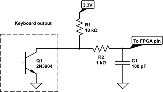
simulate this circuit – Schematic created using CircuitLab
Pull them up to 3.3V with a 10k resistor to start. If you have problems with the communication, decrease the pull up value. R2 is a current limiting resistor to protect the pin. If it accidentally gets configured as an output, you'll be glad it's there. C1 is there to prevent over and undershoot, again, protecting the pin. It is optional, and if you choose to include it, you need to be very careful. On the transition from low to high, it must charge through the pullup and current limiting resistor. That rise time must be sufficiently short that it doesn't cause the communication protocol's timing to be violated. On the transition from high to low, when the transistor turns on, it discharges through R2. That fall time will be shorter, so there is no problem there.
- 13,734
- 5
- 34
- 61
-
By works like a charm, I mean of course that I can get signals from the keyboard to the Mojo, everything after that is still utterly broken. – Void Star Nov 28 '13 at 21:08
-
I had the exact same problem. Very helpful, but one thing I couldn't find any info about is whether the KB has its own 5V pull-up resistor. If so, the above design could damage the FPGA. I measured my own PS/2 KB and found that indeed it has a 2.3kΩ pull-up resistor to 5V; therefore if you use a 10kΩ pull-up to 3.3V, the FPGA pin will be exposed to about 4.68V. If you use a 1kΩ pull-up to 3.3V, the FPGA pin will be exposed to about 3.82V (which is under the max of 4.1V). This may be safe, but it's still risky. Unless the capacitor is to stop that; I'm really not sure what it's there for. – mgiuca Aug 01 '15 at 14:21
-
Of the stack of PS/2 mice in my collection it seems they have an internal pullup to +5 volt. As a warning to anyone that wants to hook a PS/2 Mouse to their FPGA. While Keyboards seem to be compliant to the open-collector it seems many if not all mice are not. I would recommend checking the data and clock voltages of any device before you assume they are open-collector. – Matthew Whited Mar 04 '21 at 14:14