2

I am trying to create the circuit below but then the resistor is getting too hot. I think is has something to do with my power source 15V, 8A. My resistor is 51 ohms, 1/4W. Any comment please... Should I increase resistance or wattage to prevent resistor from getting very hot.

schematic

simulate this circuit – Schematic created using CircuitLab

Thanks.

clabacchio
  • 13,481
  • 4
  • 40
  • 80
user33351
  • 21
  • 1
  • 2
  • 7
    Are those diodes really LTL-307EE, or is that just what circuitlab put in for you? – Phil Frost Nov 27 '13 at 04:00
  • - [How can I efficiently drive an LED?](http://electronics.stackexchange.com/q/55823/17608) - [Calculating resistor value and power rating for LED driving](http://electronics.stackexchange.com/q/25222/17608) - [Correct formula for LED current-limiting resistor?](http://electronics.stackexchange.com/q/17179/17608) – Phil Frost Nov 27 '13 at 15:27

4 Answers4

6

For a resistor

$$p_R = \dfrac{V^2_R}{R}$$

Generally speaking, it is not a good idea to operate a resistor at its power rating.

But, assuming we do operate at 1/4W, we find:

$$V_{R_{max}} = \sqrt{0.25W \cdot 51 \Omega} = 3.57V$$

So, you really would like the voltage across the resistor to be quite a bit less than \$3.57V\$

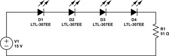
Now, the voltage across the resistor is:

$$V_R = 15V - 4 \cdot V_D$$

where \$V_D\$ is the nominal voltage across one of the diodes. So, if

$$V_D \le \dfrac{15 - 3.57}{4} = 2.86V$$

you'll be at or exceeding the maximum power rating of the resistor which will make it very hot indeed.

If this is the case, then you must increase the resistance or power rating or both.

Alfred Centauri
  • 26,502
  • 1
  • 25
  • 63
  • 1
    Or the voltage drop before the resistor. – Ignacio Vazquez-Abrams Nov 27 '13 at 04:38
  • You are reversing things. You assume that the resistor is ¼W and correctly rated for the circuit. Your reasoning is correct, but from the assumption that the power rating is somewhat correct you are calculating what the LED specs should be, whereas the LEDs should be the given and the resistor to be calculated (both resistance and power values). I'm not convinced that the type mentioned in the author's diagram is correct. – jippie Nov 27 '13 at 08:51
  • 1
    @jippie, I don't disagree with what you say *but I'm not designing the circuit, I'm analyzing it.* In particular, I'm giving a lower bound on the diode voltage *for that particular resistor value and wattage rating*. Of course, the design process is the other way around but, as you say, we don't know if the diodes in the schematic are place holders or not. – Alfred Centauri Nov 27 '13 at 13:03
2

You should first decide how much current you want the LEDs to conduct so you can select the biasing voltage across them.

If using LTL-307EE diodes as indicated in the question: For 20mA through the circuit, you need 2V across each diode, or 8V across all four.

When you know the desired current, and what the voltage needs to be across the resistor (15V-8V= 7V), you can calculate for the resistor value.

R = V/I = 7V/.02A = 350 Ohm, which will dissipate P=V^2/R= 140mW.

If you use a standard 10% resistor, the next closest value you can actually buy is 390 Ohm, which will lower the total current to ~18mA, and dissipate ~126mW.

dext0rb
  • 3,681
  • 2
  • 28
  • 41
  • Important to notice is that your 20mA and 2V are assumptions, they are specific for the LED's used. – jippie Nov 27 '13 at 08:47
  • @jippie Check the datasheet... – dext0rb Nov 27 '13 at 08:49
  • True, but the named type in the circuit diagram is the default in CircuitLab and I just think it is a bit too coincidental. What I was trying to say is that it is good to note where you got the values from, now they just appear out of nothing. Your answer is otherwise fine. – jippie Nov 27 '13 at 10:53
  • ohhhh! I didn't know that is the default for CircuitLab, now I understand everyone's doubt. :) – dext0rb Nov 27 '13 at 14:08
0

Do a web search for "LED calculator". A calculator will led you plug in the values for the LED and the supply current and tell you what resistor to use.

For the LED, you need to find the forward voltage and the continuous forward current.

I tried this with 4 of the LEDs you specify (2V, 20mA of current), and the calculator said 270 ohms. If you are using 50 ohms, you are putting far more current through the LEDs than you should, and they will likely burn out pretty quickly.

Eric Gunnerson
  • 1,216
  • 6
  • 6
0

You should probably both increase resistance and power. There exist a couple of approaches to this.

First one, search the diode's datasheet. There will be a Current-Voltage curve. Select your desired current, check what junction voltage it corresponds to. From there the new resistor needs to drop exactly the supply voltage minus the sum of all diode drops. This is done using Ohm's law.

The second approach is to plug a potentiometer in place of the resistor. Set the potentiometer to maximum resistance, power the circuit, start scrolling slowly to lower resistance. At some point the diodes will light up, then there will be increase in brightens, then brightness increasing will slow and stop, then the circuit board will catch on fire. You want to stop somewhere before the brightness stops increasing. Measure the potentiometer and that is your new resistance value. The power can be determined by the formula in Alfred's answer.

Vorac
  • 3,091
  • 5
  • 29
  • 52