7

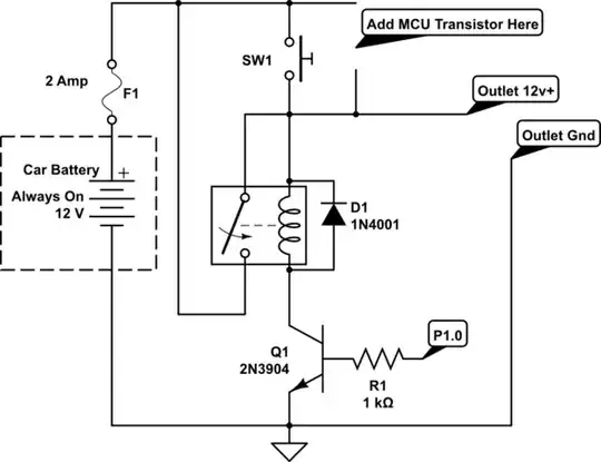
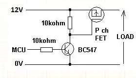
I want to replace a physical N.O. switch with a microcontroller controlled transistor. The MCU is a ~3.3v MSP430. Since this is high side, I know I need a PNP transistor, and since the voltages are different, I need a way to connect the two.

schematic

simulate this circuit – Schematic created using CircuitLab

I thought of using either a Sziklai Pair or a modified inverting npn/pnp pair.

schematic

simulate this circuit

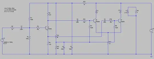
Is there a practical difference between the two? And is there any significant (Greater than 1mA) current draw?

As a note, if it is important, the point marked "?" at the PNP's collector, can be tied to the 12v source. Would this be an issue? And I will only need to enable the pair for under 0.5 Seconds, long enough to turn the relay on (typically 10mS??).

Passerby
  • 72,580
  • 7
  • 90
  • 202
  • Have a look at [this thread](http://electronics.stackexchange.com/a/39429/7036). It also deals with high side switch controlled by a μC. That question revolves around switching a voltage divider on and off. (Related but not a duplicate.) – Nick Alexeev Nov 20 '13 at 23:09
  • Are you saying that the relay in your top circuit is undesirable and that you wish to replace it with an electronic device that shorts SW1 out? For your other two circuits what is the relay shown and what does it do? – Andy aka Nov 21 '13 at 08:35
  • @Andyaka I simply want to replace SW1. The relay in both circuits are the same. – Passerby Nov 21 '13 at 08:39
  • The relay contact is in parallel with the switch and that is what confuses me because it appears to do the job of what you want already hence my question. – Andy aka Nov 21 '13 at 09:10
  • @Andyaka oh, its a way of making the relay latching. The switch provides a path to enable the relay, at which point, it stays on until power is cut. – Passerby Nov 21 '13 at 09:16
  • Would using a MOSFET (P-channel) in place of Q4 be an option for you? – JimmyB Nov 21 '13 at 09:30
  • @HannoBinder sure, but I have zero experience using them, or how to select them. – Passerby Nov 21 '13 at 09:39
  • For your current demand most any P-MOSFET will do that is able to switch some 14V+ (don't know any that doesn't...). Then just swap it in for Q4 and you're done. - There are also FET-based, µC-compatible "Smart High Side Switches" (like those "PROFET"s for instance) which take all the hassle off you, provide rock-solid operation in automotive environments and can probably even replace the existing relay if you'd like. Might be a little over the top for this case but for homebrew use I find the ease-of-use worthwhile the prices of $2-$4 per unit. – JimmyB Nov 21 '13 at 10:17

2 Answers2

3

The left circuit you show will not work, because the emitter of Q1 will not rise above its base.

The right circuit is a disaster, because when Q2 conducts there is nothing in its path (via the BE of Q4) to limit the current.

A good circuit could be either

  • the right circuit, but replace Q4 with an NPN type (but now the circuit inverts)
  • the right circuit, but add a 1k resistor in series with the collector of Q2
Wouter van Ooijen
  • 48,407
  • 1
  • 63
  • 136
  • So for the left, the Q1/NPN emitter, before the circuit is engaged, will be tied to ground through the relay's coil (~50 Ohm). So the 3.3v base signal wouldn't be enough? After the pair engages, which enables the relay and brings the emitter to 12v, the pair no longer need to be used. Looking at relay sheets, I only really need at most 10 milliseconds. So would it still not work? – Passerby Nov 20 '13 at 22:52
  • And if I change the right to a npn, Would it be enough for a 50 to 100 ohm relay, even though it is high side switching? In that case, couldn't I simply remove q4 entirely, and put Q2 directly on the high side of the relay coil? – Passerby Nov 20 '13 at 22:53
  • 1
    From your comments (answer is NO to both) I think that you don't understand the working of an emitter follower. In such a circuit (the left circuit is a modified E.F., your proposal would make the right circuit one as well) the emitter trails the base voltage (minus ~ 0.6V). Hence the relais never gets the full 12V. – Wouter van Ooijen Nov 21 '13 at 06:32
  • Of course I don't, hence why I'm asking :P And the left is this http://en.wikipedia.org/wiki/Sziklai_pair a Sziklai Pair, or Compound transistor pair. I am trying to understand what you are saying, but I can't make much heads or tails out of it. – Passerby Nov 21 '13 at 07:04
  • Just try to follow each step in the reasoning. For the left diagram, collector current through Q3 requires base current through Q3 == collector current through Q1, which requires base current through Q1. The latter requires that Q1's base is at a (~ 0.6V) higher potential than its emitter. Hence the emitter will never be higher than the base. – Wouter van Ooijen Nov 21 '13 at 07:27
  • How about the right circuit, but moving R2 to the emitter of Q2? – supercat Nov 21 '13 at 16:47
  • @supercat: that is yet another possibility. – Wouter van Ooijen Nov 21 '13 at 19:03
  • 1
    @Passerby: I'm guessing you've figured this out by now, but for appropriate schematic [2nd solution of Wouter] look at fig 3-30 in https://books.google.com/books?id=G5jGKbsCNYcC&pg=PA42 for instance. You need a resistor to limit the current through the transistors when the switch is on. – Fizz Nov 28 '15 at 07:24
3

I'd use a P channel MOSFET and a low side BJT like this: -

enter image description here

The 12V in my diagram connects to the node with the fuse in your diagram and where I have shown load, this is outlet 12V+ and gnd on your diagram. Hope this makes sense.

The MCU will turn on the BJT which conducts enough current to pull the FET's gate down to near ground. This turns the FET on.

If there are any worries about protecting the FET's gate (due to it being an automotive application), insert 1k ohm directly in series with the BJT's collector and put a 15V zener diode across the gate's 10k ohm.

Choosing the right P channel FET is all about rating it for the desired load on the outlet. Let me know what sort of load it is, if you want.

Andy aka
  • 434,556
  • 28
  • 351
  • 777