3

I am trying to build a temperature controlled 555 circuit to drive a cpu fan (used for cooling my entertainment center)

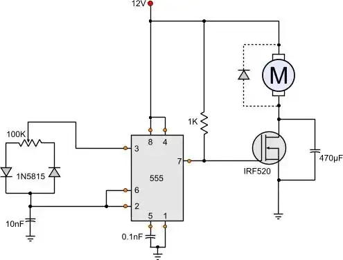
I built this using slightly different diodes and MOSFET, and it works great (until you hook up the power backwards and get that distinctive pop of and poof of smoke from a blown up 555). Circuit: -

enter image description here

anyway, now I want to make it temperature controlled. I have a few tmp36 sensors laying around as well as an AD592 and a AD22100, so I can use whichever will work best. how could I go about converting this circuit to vary based on the temp? Let's say lowest speed below 75 F and full out above 100, but I would love to learn, so if you could explain the calculations, that would be great. I feel like this should be easy, and I am kind of just missing something, but who knows.

Thanks!

Andy aka
  • 434,556
  • 28
  • 351
  • 777
lkrasner
  • 71
  • 2
  • 5
  • 2
    You'll find it a lot less painful to use a MCU. Some even have thermal sensors built-in. – Ignacio Vazquez-Abrams Nov 19 '13 at 02:07
  • yeah, I know that would be easier, but I want to learn how to do this, plus, I'd rather not waste an arduino or spend more on something when I already have these parts around – lkrasner Nov 19 '13 at 02:13
  • http://www.taydaelectronics.com/ic-integrated-circuits/microcontrollers/attiny85-attiny85-20pu-8-bit-20mhz-microcontroller-ic.html – Ignacio Vazquez-Abrams Nov 19 '13 at 02:14
  • 1
    thanks, but once again, now I really want to know how to do it with a 555, sometimes it's not about the easiest way, I want to learn – lkrasner Nov 19 '13 at 02:16
  • Can you put a thermistor where the potentiometer is? – Samuel Nov 19 '13 at 02:17
  • well, that was my thought, but isn't the pot a variable voltage divider in this case, so I can't really just pop in the temp sensor/thermistor – lkrasner Nov 19 '13 at 02:19
  • You could create a voltage divider with it though. – Ignacio Vazquez-Abrams Nov 19 '13 at 02:20
  • how might I go about that and still have it be variable – lkrasner Nov 19 '13 at 02:22
  • Use a fixed value for the other resistor. – Ignacio Vazquez-Abrams Nov 19 '13 at 02:25
  • alright, I'll give that a shot – lkrasner Nov 19 '13 at 02:27
  • that seems to be working, I'll just have to test it to get the resistor value right – lkrasner Nov 19 '13 at 02:56
  • 2
    Instead of "wasting" an arduino (which are, in my rather jaded opinion, a waste of space in the first place), you could use a PIC10F or 12F with a PWM output and an ADC input to implement a PID controller in much the same space as a 555. – markt Nov 19 '13 at 07:15
  • @Ikrasner -If you analyze the circuit you'll see that the 555 is doing two separate tasks - an astable clock and a variable mark space ratio. This makes it difficult to modify the existing circuit. However, if you re-design the circuit to work with two 555s (astable triggering monostable) then you can alter the monostable period with a thermistor (CR period) - i.e. control the mark/space ratio. – JIm Dearden Nov 19 '13 at 08:28
  • well, a thermistor and a resistor seems to be working ok (using just 2 legs of a pot to test the values that work best, so I think I got it, but thanks for all the comments anyway. – lkrasner Nov 19 '13 at 13:44

1 Answers1

2

You can accomplish temperature feedback by connecting the analog voltage out pin of the TMP36* to pin 5 of the 555. A temperature increase will increase the voltage at pin 5 of the 555, this increased voltage will increase the "on" time of the 555 as I've outlined elsewhere. This will, in turn, increase the voltage that the fan is experiencing and thus its speed! You will need to tune the size of the potentiometer and capacitor to suit the application.

*Connect the other two pins to \$V_\text{cc}\$ and ground according to the datasheet.

Paul Stiverson
  • 226
  • 1
  • 6