6

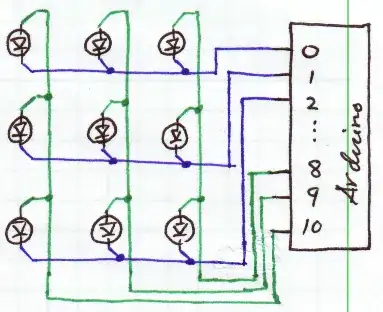
i am trying to get a 3x3 matrix with multiplexing up and running. here is my setup:

alt text

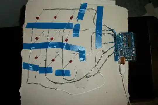
i have connected each rows cathodes and each columns anodes and connected that one to pins 0,1,2 resp. 8,9,10

the only thing i can get to light is the lowest row, but if i want to light the middle row for example with this:

digitalWrite(8, HIGH);     
digitalWrite(9, HIGH);     
digitalWrite(10, HIGH);     

digitalWrite(0, HIGH);
digitalWrite(1, LOW);
digitalWrite(2, HIGH);

nothing happens.

is my wiring setup wrong maybe?

clamp
  • 325
  • 3
  • 5
  • 11
  • 1
    are you sure you've got the polarity of all your LEDs right? – vicatcu Jan 15 '11 at 21:23
  • 2
    do you have the requisite pin modes set to output? e.g. pinMode(8, OUTPUT); pinMode(9, OUTPUT); pinMode(10, OUTPUT); pinMode(0, OUTPUT); pinMode(1, OUTPUT); pinMode(2, OUTPUT); – vicatcu Jan 15 '11 at 21:24
  • @vicatu, I'd upvote that as an answer. (Er, in 2 hours, when my daily limit clears.) – tyblu Jan 15 '11 at 21:50
  • Thank you for the photo. Looks like you are well on your way towards an awesome project. :-) – davidcary Apr 01 '11 at 20:47

4 Answers4

6

Here's a sketch of what you've described for clarity and benefit to others:

Good things to do at this point:

  • Make sure you have current limiting resistors in series with each LED. 560Ω will limit to ~6mA. If these are not presently in place, some LEDs may be burned out, so check them. The ATmega128/328 (whichever is on your board) is limited to *20mA per pin**.
  • Verify that the pins are actually going high or low when you program them to do so, with a voltmeter or logic probe.

*I must correct myself, here. This is the actual restriction:

27.1 Absolute Maximum Ratings
NOTICE: Stresses beyond those listed under “Absolute Maximum Ratings” may cause permanent damage to the device. This is a stress rating only and functional operation of the device at these or other conditions beyond those indicated in the operational sections of this specification is not implied. Exposure to absolute maximum rating conditions for extended periods may affect device reliability. ...

DC Current per I/O Pin             40.0 mA  
DC Current V and GND Pins       200.0 - 400.0 mA 

...
Although each I/O port can sink more than the test conditions (20 mA at VCC = 5V, 10 mA at VCC = 3V) under steady state conditions (non-transient), the following must be observed: TQFP and QFN/MLF Package: 1] The sum of all IOL, for all ports, should not exceed 400 mA. 2] The sum of all IOL, for ports A0 - A7, G2, C3 - C7 should not exceed 100 mA. 3] The sum of all IOL, for ports C0 - C2, G0 - G1, D0 - D7, XTAL2 should not exceed 100 mA. 4] The sum of all IOL, for ports B0 - B7, G3 - G4, E0 - E7 should not exceed 100 mA. 5] The sum of all IOL, for ports F0 - F7, should not exceed 100 mA. If IOL exceeds the test condition, VOL may exceed the related specification. Pins are not guaranteed to sink current greater than the listed test condition.

tyblu
  • 8,167
  • 6
  • 40
  • 70
  • 1
    One resistor for each row driver pin, and one resistor for each column driver pin (in this case, 6 resistors) will work great, whether the software does row scanning or column scanning or both. Most [LED matrix array](http://opencircuits.com/PointLess_LED_Array) only put resistors on the column driver pins, or only put resistors on the row driver pins. (In this case, 3 resistors). That works OK as long as the software and the hardware agree on whether you are doing row scanning, or doing column scanning. – davidcary Apr 01 '11 at 22:09
2

Without current limiting, you are counting on the micro to limit the current. By turning on several outputs at one time it is consuming a lot of current. I would add 3 resistors to the high bus, 330-560 ohms to the outputs on 8, 9, 10. Turn on only one led at a time. If you need the appearance of several led's on at one instance you can clock the outputs faster in succession.

SteveR
  • 1,622
  • 9
  • 12
1

I don't think you can multiplex like this. You are using all those pins as outputs i.e. digitalWrite(X, HIGH) makes the output of pin X +5 volts. To use two outputs together you need some kind of switch (e.g. an AND gate or some configuration of transistors). I'd say you'd be better off using a shift register (3 inputs to 8) of just use 9 output lines from the board, one for each LED, then write the code for controlling the matrix.

Hope this helps :)

1

Your setup looks correct. However Aruino digital pins 0 and 1 are also serial in/out. If you are also using serial communication you cannot use them as digital input. Try using other pins.

tuupola
  • 1,657
  • 2
  • 17
  • 21